An Affordable Lithium Boat Battery

Zing

Well-known member
Joined
7 Feb 2014
Messages
8,080
Visit site
If you have a high powered BMS it will have a heavy duty relay/contactor as part of the BMS system. If you look up the specifications for this device, or these devices (sometimes more than one can be used) it will have a maximum current value. The BMS will not limit the maximum current, but ithe contactor will be damaged if its current limits are exceeded. Therefore the BMS sytem has a limited maximum current.

Common used marine contactors are pictured below, although there are many choices:
View attachment 161287
View attachment 161288
I’ve got the second one, but the BMS does not consider current. Actually the contactor can pass much a higher current briefly, such that there is no feasibly likely load it can’t cope with. Note BTW that individual consumers are all fused.
 

noelex

Well-known member
Joined
2 Jul 2005
Messages
4,834
Visit site
there is no feasibly likely load it can’t cope with.
That is how you want to design the system.

The maximum output of the BMS (or the combined output of the multiple BMS units) should not be less the highest house current draw.

I think you are confusing a BMS that actively limits the current (which is a feature of only some units) and a BMS that has a current limit because of the components used in the construction. This latter limitation applies to all BMS systems.

The bottom line is do not ignore the current limit of the BMS. Always make sure this is adequate. The maximum current draw of many BMS units is low and all have a finite limit so it is an important design parameter.
 
Last edited:

Zing

Well-known member
Joined
7 Feb 2014
Messages
8,080
Visit site
That is how you want to design the system.

The BMS (or the combined output of the multiple BMS units) should not be failing with the highest house current draw.

I think you are confusing as BMS that actively limits the current (which is a feature of some units) and a BMS that has a current limit because of the components used in the construction. This applies to all BMS systems.

The bottom line is do not ignore the current limit of the BMS. Always make sure this is adequate. The maximum current draw of many BMS units is low and all have a finite limit so it is an important design parameter.
Note, I specifically selected a BMS that didn’t have current limits. On my boat it would have been a risk and safety issue to be constrained that way, which of course is the way most BMSs work.
 

geem

Well-known member
Joined
27 Apr 2006
Messages
8,043
Location
Caribbean
Visit site
Note, I specifically selected a BMS that didn’t have current limits. On my boat it would have been a risk and safety issue to be constrained that way, which of course is the way most BMSs work.
Every current conducting device has current limits. You can have a BMS thst doesn't pass the load current but instead controls a contactor that passes the current, but even these contactor have a current rating. Nothing is current unlimited. The contactor will have a current rating. Its likely to be significantly high but not unlimited
 

Zing

Well-known member
Joined
7 Feb 2014
Messages
8,080
Visit site
Every current conducting device has current limits. You can have a BMS thst doesn't pass the load current but instead controls a contactor that passes the current, but even these contactor have a current rating. Nothing is current unlimited. The contactor will have a current rating. Its likely to be significantly high but not unlimited
Of course. Unfeasibly high though in the case of the BlueSea contactor. Not requiring therefore any protection by a BMS beyond its fuses.
 

migs

Active member
Joined
5 Jul 2011
Messages
146
Visit site
'Nice write up @migs. Got any more details on your BMS and relay/contactor used?'

Thanks for your comment.

There are a couple of reasons why I haven't posted details of the BMS on github yet. One is the (faint) hope of licensing the design to an enterprising manufacturer; the other is that I'm concerned that somebody with insufficient experience might make one and cause thousands of pounds worth of damage to their boat (or worse), and I'll get the blame...

Our BMS is based on a TI bqxx AFE and an nRF52xx programmed in C++; the associated Bluetooth application is written in JavaScript, html and css. The bistable relay is simply driven by two small SOT-23 size IRLMLxx n-channel mosfets, and requires 80ms ~3A pulses for set and reset.

The bistable relay we used is £83 from RS, or the Hongfa equivalent (HFV12) is about £25 from Switchtec.

https://docs.rs-online.com/a0c6/0900766b81394ae4.pdf

https://source.hongfa.com//pdf/web/...Product/PDF/HFV12_en.pdf?timestamp=1691224907
 
Last edited:

Zing

Well-known member
Joined
7 Feb 2014
Messages
8,080
Visit site
So it's rated st 500A then. Not unlimited?
No, it’s 1450A actually under the intermittent load I mentioned in my post when I said there was no feasible load it couldn't cope with. Note fuses will have blown long before that limit.

Your use of the word unlimited misrepresents what I said.
 

Kelpie

Well-known member
Joined
15 May 2005
Messages
7,767
Location
Afloat
Visit site
'Nice write up @migs. Got any more details on your BMS and relay/contactor used?'

Thanks for your comment.

There are a couple of reasons why I haven't posted details of the BMS on github yet. One is the (faint) hope of licensing the design to an enterprising manufacturer; the other is that I'm concerned that somebody with insufficient experience might make one and cause thousands of pounds worth of damage to their boat (or worse), and I'll get the blame...

Our BMS is based on a TI bqxx AFE and an nRF52xx programmed in C++; the associated Bluetooth application is written in JavaScript, html and css. The bistable relay is simply driven by two small SOT-23 size IRLMLxx n-channel mosfets, and requires 80ms ~3A pulses for set and reset.

The bistable relay we used is £83 from RS, or the Hongfa equivalent (HFV12) is about £25 from Switchtec.

https://docs.rs-online.com/a0c6/0900766b81394ae4.pdf

https://source.hongfa.com//pdf/web/...Product/PDF/HFV12_en.pdf?timestamp=1691224907
Just to add another option, I decided to buy an off the shelf BMS and then use it to trip an external relay. The plan was to use the relay on the inverter, which is my only big load, and everything else would go through the BMS itself.

In the end I didn't install the relay, I 'temporarily' set the system up with everything going through the BMS. Ran like that for a year, maxing out the BMS current on an almost daily basis. When they brought out the larger 200A version, I swapped to that. I don't know how long the 120A unit would have lasted with that sort of treatment, I was probably pushing my luck. But with the 200A version, which has much better cooling and bigger terminals, everything remains quite cool to the touch and I expect it to last a long time. At under £100 I think it's pretty good value for a plug and play solution.
 

PaulRainbow

Well-known member
Joined
16 May 2016
Messages
17,245
Location
Suffolk
Visit site
No, it’s 1450A actually under the intermittent load I mentioned in my post when I said there was no feasible load it couldn't cope with. Note fuses will have blown long before that limit.

Your use of the word unlimited misrepresents what I said.
You initially said "No. Not all have a current limit."

Using the BlueSea relay your maximum working current through the BMS system is therefore 500a.

The 1450A figure you quote is only for 30 seconds.
 

Zing

Well-known member
Joined
7 Feb 2014
Messages
8,080
Visit site
You initially said "No. Not all have a current limit."

Using the BlueSea relay your maximum working current through the BMS system is therefore 500a.

The 1450A figure you quote is only for 30 seconds.
Incorrect. Those words were in the context of my BMS, which does not monitor current, hence no current limit. I also did make it clear on the current limit of the BlueSea that was the intermittent rating. Nothing to correct here I’m so sorry.
 

geem

Well-known member
Joined
27 Apr 2006
Messages
8,043
Location
Caribbean
Visit site
No, it’s 1450A actually under the intermittent load I mentioned in my post when I said there was no feasible load it couldn't cope with. Note fuses will have blown long before that limit.

Your use of the word unlimited misrepresents what I said.
The relay is rated to 500A, intermittently rated for 1450A, not constant rated for 1450A. Its not a case of having 'no current limits'. Your words
 

Zing

Well-known member
Joined
7 Feb 2014
Messages
8,080
Visit site
The relay is rated to 500A, intermittently rated for 1450A, not constant rated for 1450A. Its not a case of having 'no current limits'. Your words
That's an out of context quotation by you. It looks like a wilful misrepresentation. It's tiresome.
 

PaulRainbow

Well-known member
Joined
16 May 2016
Messages
17,245
Location
Suffolk
Visit site
The relay is rated to 500A, intermittently rated for 1450A, not constant rated for 1450A. Its not a case of having 'no current limits'. Your words
It isn't even that, the intermittent rating is only 700A. the 1450A figure is engine starting, for 30 seconds max.But, of course, those figures are entirely irrelevant in the context of the BMS system, which is limited to 500A.
 

gregcope

Well-known member
Joined
21 Aug 2004
Messages
1,624
Visit site
'Nice write up @migs. Got any more details on your BMS and relay/contactor used?'

Thanks for your comment.

There are a couple of reasons why I haven't posted details of the BMS on github yet. One is the (faint) hope of licensing the design to an enterprising manufacturer; the other is that I'm concerned that somebody with insufficient experience might make one and cause thousands of pounds worth of damage to their boat (or worse), and I'll get the blame...

Our BMS is based on a TI bqxx AFE and an nRF52xx programmed in C++; the associated Bluetooth application is written in JavaScript, html and css. The bistable relay is simply driven by two small SOT-23 size IRLMLxx n-channel mosfets, and requires 80ms ~3A pulses for set and reset.

The bistable relay we used is £83 from RS, or the Hongfa equivalent (HFV12) is about £25 from Switchtec.

https://docs.rs-online.com/a0c6/0900766b81394ae4.pdf

https://source.hongfa.com//pdf/web/...Product/PDF/HFV12_en.pdf?timestamp=1691224907

Thanks. I get the concerns, although doubt 96% of people would blame you for anything if someone decided to download and make one then damage something.... The other 4% believe in aliens and all sorts so no pleasing them on anything.

That relay looks interesting. I cannot find any quiescent current on the datasheets so I assume its near zero.

At a 260A rating you are at the top end of many 35mm2 cable (cool/outside conduit) and some connectors (e.g. Anderson 170A) hence why they sensibly suggest 50mm2.

What size cables do you have?
 

GHA

Well-known member
Joined
26 Jun 2013
Messages
12,517
Location
Hopefully somewhere warm
Visit site
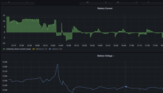
Since I'm in here...... back to "float which isn't really float", I have 2 x victron smartsolar regulators talking to a smarthunt set to bulk until 13.85v then "float" of 13.35v. Interestingly the regs don't exactly track the smartshunt voltage, fridge cycling shows them taking a moment to wake up then pull the voltage back up. Available output from solar can easily keep the fridge powered but they don't straight away. Those settings work for me anyway, never go too high up the knee & after that the voltage is below anything considered harmful.

1691269726093.png
 

Chiara’s slave

Well-known member
Joined
14 Apr 2022
Messages
7,737
Location
Western Solent
Visit site
The techy part of me would love to go lithium. I think it could make financial sense. But we don’t have engine and house batteries, just 1 to rule them all. It therefore starts the engine, and is charged by the engine. I don’t see a way to resolve this, that’s not suitable to charge a LiFe battery? The solar and load are no issue. As the engine is a Honda 15 o/b, should we run a motorbike lead acid battery as the engine battery and have a Li house battery? Fairly big rewire job there, and a deal of extra complexity. Or do we live out our sailing days with lead? We do have some charging issues in winter, when running the heating a lot.
 

geem

Well-known member
Joined
27 Apr 2006
Messages
8,043
Location
Caribbean
Visit site
The techy part of me would love to go lithium. I think it could make financial sense. But we don’t have engine and house batteries, just 1 to rule them all. It therefore starts the engine, and is charged by the engine. I don’t see a way to resolve this, that’s not suitable to charge a LiFe battery? The solar and load are no issue. As the engine is a Honda 15 o/b, should we run a motorbike lead acid battery as the engine battery and have a Li house battery? Fairly big rewire job there, and a deal of extra complexity. Or do we live out our sailing days with lead? We do have some charging issues in winter, when running the heating a lot.
A motorbike battery and seperate lead would be the way to go IMHO.
It took me 2 weeks to rewire my boat for lithium. We have numerous charging sources that were all configured for the lead batteries. Lots to change
 
Top