Making a DIY emergency VHF aerial

BlueChip

Active member
Joined
24 Aug 2004
Messages
4,847
Location
Bucks/Plymouth
Visit site
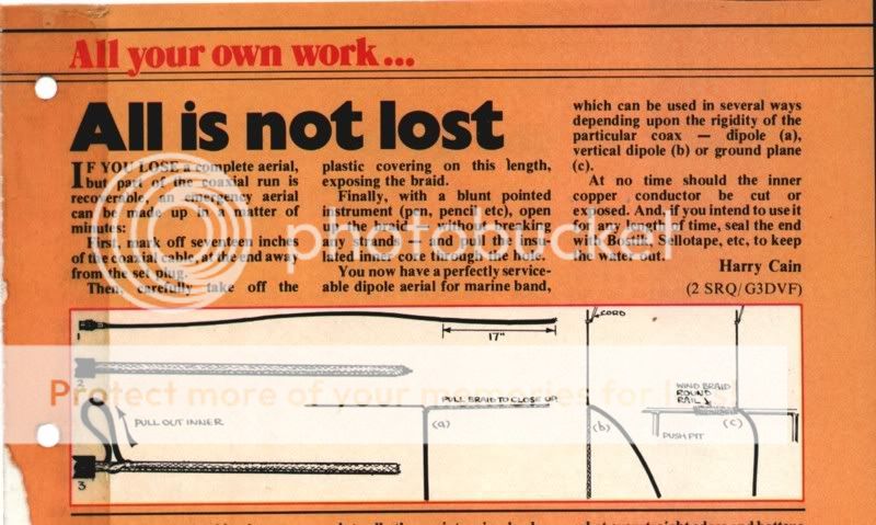
I read somewhere that an emergency VHF aerial could be made by stripping some coax, and making a T with the core wire and shield.
Is this possible, how long would the T part need to be?
 

john_morris_uk

Well-known member
Joined
3 Jul 2002
Messages
27,310
Location
At sea somewhere.
yachtserendipity.wordpress.com
16 inches long.
I think you may be a touch short. The calculations for a dipole at 156 Mhz come out at 1ft. 6 - 1/32in. or 0.457 M for each leg.

It ought to be empasised that this is ONE HALF of the dipole. Strip the coax back by 0.457 metres and extract the inner from the outer. (Its a bit fiddly) pull the braid out and cut it off at 0.457 M long as well (it will get longer when its strectched out with the inner removed). The whole dipole from the end of the 'inner' to the end of the braid streached out in a line should be 3' 1/16"

Remember not to touch the wires when you are transmitting as RF can burn you and its nasty stuff at high power. It might also be worth remembering that the polarisation of most Marine VHF is vertical - so tape the home made emergency dipole to a wooden boat hook and hold it vertically.
 

FullCircle

Well-known member
Joined
19 Nov 2003
Messages
28,220
Visit site
We will clash just slightly on this John.

Channel 16, which is likely if you are using an emergency antenna, is 156.800Mhz

Therefore the 1/4 wavelength vertical antenna for Ch 16 should be 1ft. 5 - 15/16in. or 0.455 M

If you were considering the whole range of Marine VHF - then that is 156.000 to 161.975 ( including M2 and the AIS)

M2 is 161.425 requiring 1ft. 5 - 13/32in. or 0.442 M

/pedant off
 

VicS

Well-known member
Joined
13 Jul 2002
Messages
48,222
Visit site
A couple of links that may be of interest

http://www.irational.org/sic/radio/omni-aerial.html

http://www.ac6v.com/antprojects.htm

and an item from a very old PBO

975885de.jpg
 

bbg

Active member
Joined
2 May 2005
Messages
6,780
Visit site
Just out of curiosity, if you are considering the need for an emergency antenna, why not just carry a spare? Possibly even a purpose built emergency antenna?
 

BlueChip

Active member
Joined
24 Aug 2004
Messages
4,847
Location
Bucks/Plymouth
Visit site
Just out of curiosity, if you are considering the need for an emergency antenna, why not just carry a spare? Possibly even a purpose built emergency antenna?

This is not for use on board, I ordered a Comar AIS multi last week from Malthouse and if it arrives in time I'll take it to Spain with me on Friday. I've got a place up on the cliffs near Moraira with a clear view of the Med and I thought it would be interesting to actually know what the ships we see going past all the time actually are and what the range is.
I dont know whether they would accept a VHF aerial in my hand luggage so I figured the easiest way is to make one up when i get there. Thanks to the replies this looks like it will work ok.
 

Bilgediver

Well-known member
Joined
6 Jun 2001
Messages
8,090
Location
Scotland
Visit site
We will clash just slightly on this John.

Channel 16, which is likely if you are using an emergency antenna, is 156.800Mhz

Therefore the 1/4 wavelength vertical antenna for Ch 16 should be 1ft. 5 - 15/16in. or 0.455 M

If you were considering the whole range of Marine VHF - then that is 156.000 to 161.975 ( including M2 and the AIS)

M2 is 161.425 requiring 1ft. 5 - 13/32in. or 0.442 M

/pedant off


No Need to clash boys as you are both right.....:D


The T is a dipole so the total length is as said which is half made up of braid and half the centre conductor.


You are describing a 1/4 wave antenna where all you do is strip back the insulation and shielding for about 16 " leaving the centre conductor exposed. This will be adequate.
 

JohnTH

New member
Joined
7 Mar 2009
Messages
545
Location
Dalgarven, Ayrshire
Visit site
My emergency VHF aerial is cunningly disguised my flag pole and mounted, like most others, on the transom.

There are numerous ways of converting your flag pole to an aerial. A long drill then poking wire up the middle. A slot routed lengthwise and filled with copper wire and resin. How about building it like a split cane fishing rod.

Whatever way, radio range is limited by line of site of aerials. High is best!

Aerials are "tuned" with a Voltage Standing Wave Ratio (VSWR) meter. Mine is optimised at channel 16.

Someone is going to do all the science (I can just feel it in my water) for us but a half wave dipole at CH 16 is about one metre long. Start with your wire just a bit longer then trim it down for optimum VSWR. Seal everything with whatever turns you on and there you have it!


73s de

Johnth
 

William_H

Well-known member
Joined
28 Jul 2003
Messages
13,670
Location
West Australia
Visit site
VHF antenna

Quote
You are describing a 1/4 wave antenna where all you do is strip back the insulation and shielding for about 16 " leaving the centre conductor exposed. This will be adequate.[/QUOTE]

This is a bit misleading. An antenna must have 2 connections like a battery. The exposed 17 inches of inner wire is good but needs to have either 17 inches of braid laid out as well or the braid needs to be attached to a large area of conductor. Known as the groundplane. (Oten an Al mast.)
The variation in actual length comes from what is known as end effect. The larger the conductor diameter the more the optimum length is reduced by a few %. The longer figure quoted may be theoretical 1/4 wavelength but actual should be a little shorter. olewill
 

st599

Well-known member
Joined
9 Jan 2006
Messages
7,243
Visit site
Quote
You are describing a 1/4 wave antenna where all you do is strip back the insulation and shielding for about 16 " leaving the centre conductor exposed. This will be adequate.

This is a bit misleading. An antenna must have 2 connections like a battery. The exposed 17 inches of inner wire is good but needs to have either 17 inches of braid laid out as well or the braid needs to be attached to a large area of conductor. Known as the groundplane. (Oten an Al mast.)
The variation in actual length comes from what is known as end effect. The larger the conductor diameter the more the optimum length is reduced by a few %. The longer figure quoted may be theoretical 1/4 wavelength but actual should be a little shorter. olewill[/QUOTE]

You also need to consider the velocity factor. (i.e. the speed of light is different in a solid to in free space)
 

JohnTH

New member
Joined
7 Mar 2009
Messages
545
Location
Dalgarven, Ayrshire
Visit site
Aerial design is a black art, something like witch craft! There are some who want the ground plane to be teased out of the coax and hung vertically and there are those who don’t.

Meantime, back in the real world for this application, it does not matter. The ground plane element will be “seen” as that piece of screen that is reflected by the driven element.

For this purpose a good one to one (or as close as possible) vswr is important at channel 16. The easy way to do this is to nibble away at your vertical radiator (having made it just too long) until the correct reading is achieved on the meter. This reading WILL be different on other channels.

Remember KISS.

73s de
Johnth
 

Billjratt

Active member
Joined
9 Sep 2004
Messages
2,963
Location
Firth of Clyde
Visit site
I've tried several coax dipoles and never had really good results, however, a "J" is what is inside the white fiberglass rods you see on mobos. (3dB gain....)
A "J" can be easily made using household wire and duct tape, short leg 355mm, long leg 1420mm, coax soldered 35mm up from bottom bend which is radiused about 10mm.
The thing is tuned by slightly varying the gap between the legs of the j and then folding duct tape over to stabilise. a bit of string at the top to hang it up somewhere and a suitable plug on the other end of the coax and you're set - if you can find something non metallic to hang it from. (I do have a SWR meter to tune with)
 
Top