CAV starter motor rebuild

snibble

Member
Joined
6 Apr 2020
Messages
35
Visit site
Hello everyone. Bit of an epic for a first post but like so many I'm on lockdown and bored. I used to sail the solent but not for years and I originally posted this on a canal boat site. It certainly has more relevance here so just for interest here it is.
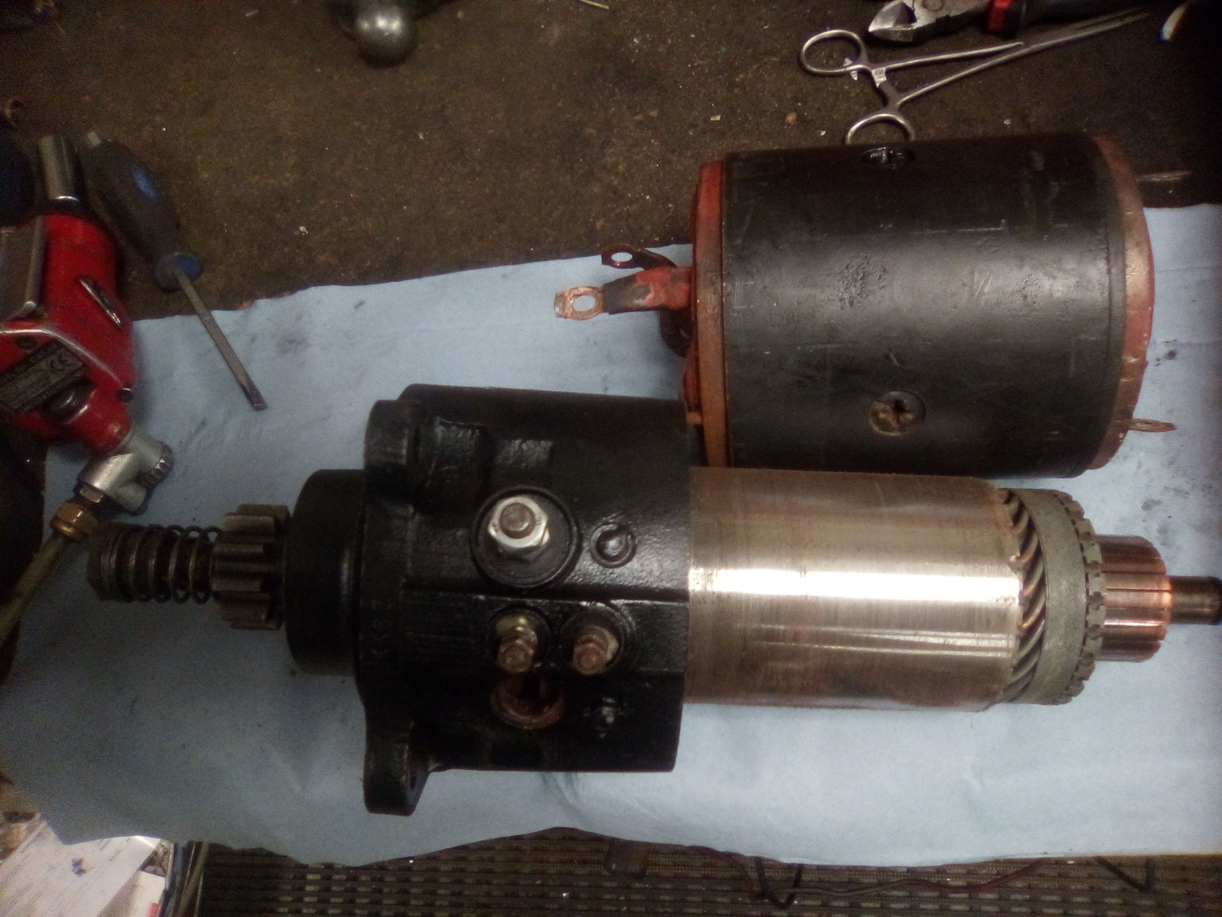
There's plenty of these things out there although they're a bit antiquated now. I thought I'd go through a rebuild, more for entertainment than information. In fact, it's more likely to put anyone off a DIY job than help!
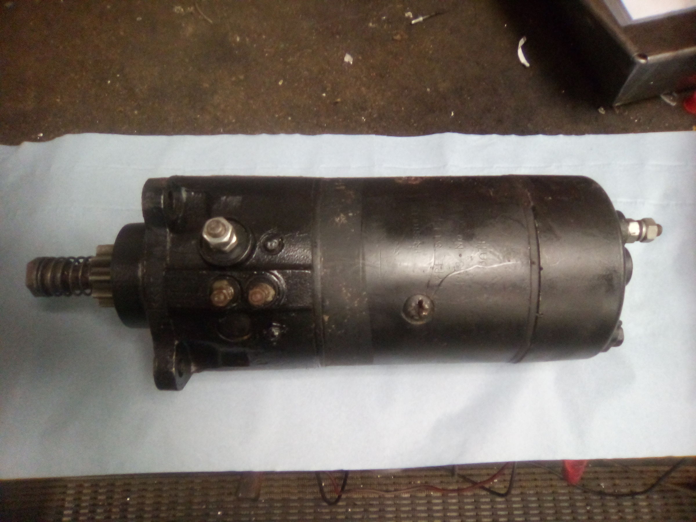
IMG_20200205_092854.jpg
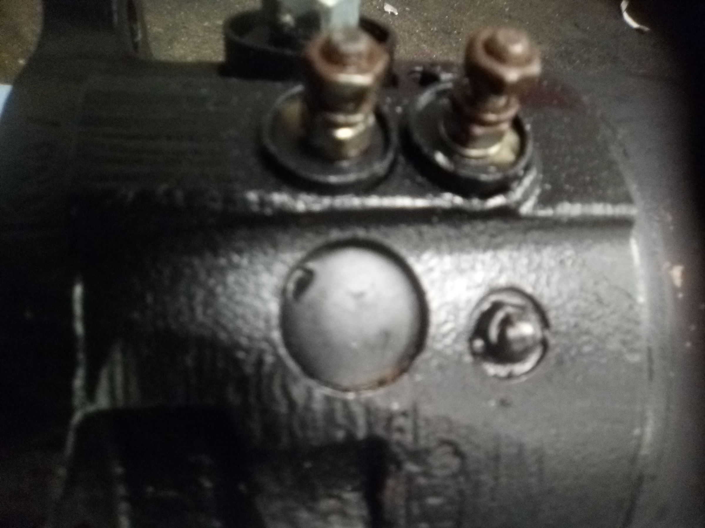
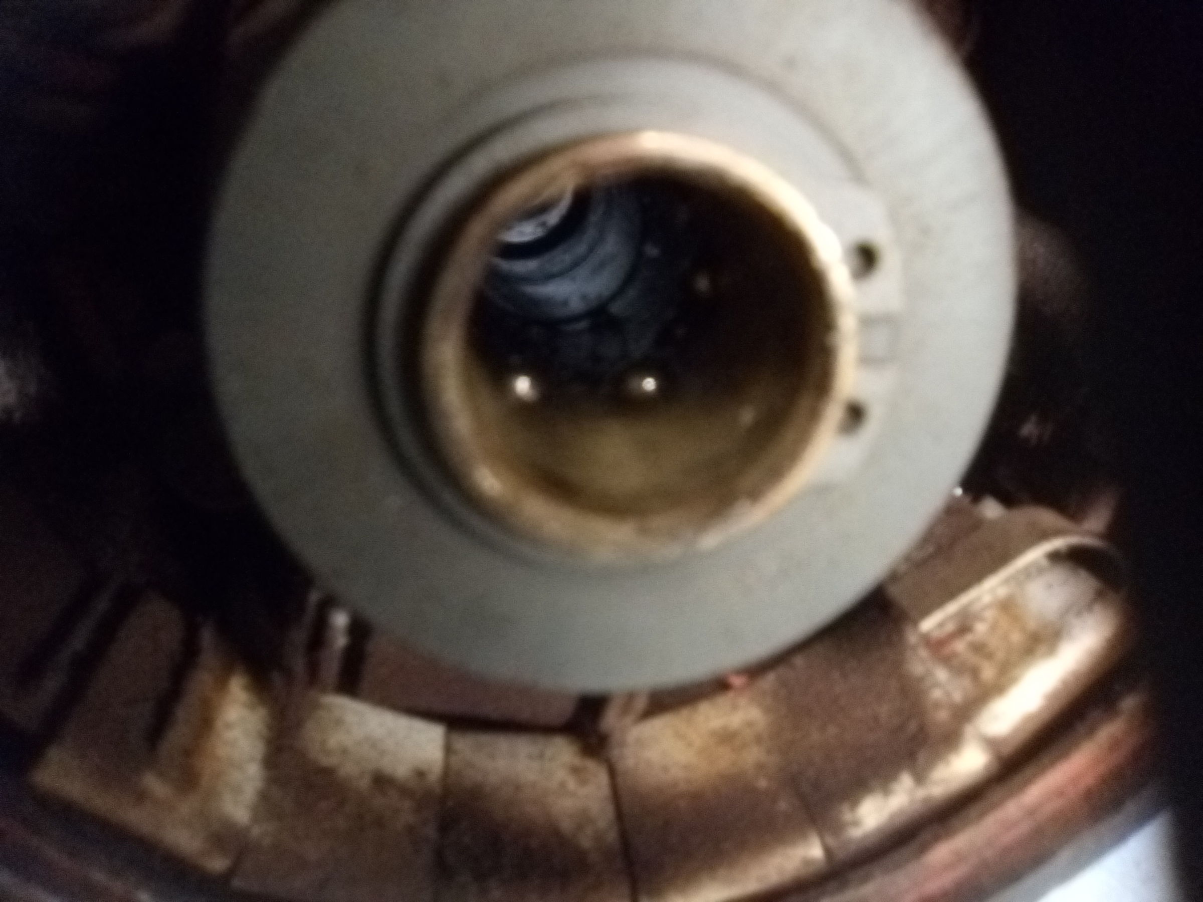
Back end first. Two screws. Behind the cover is a spring loaded ball and a top hat.
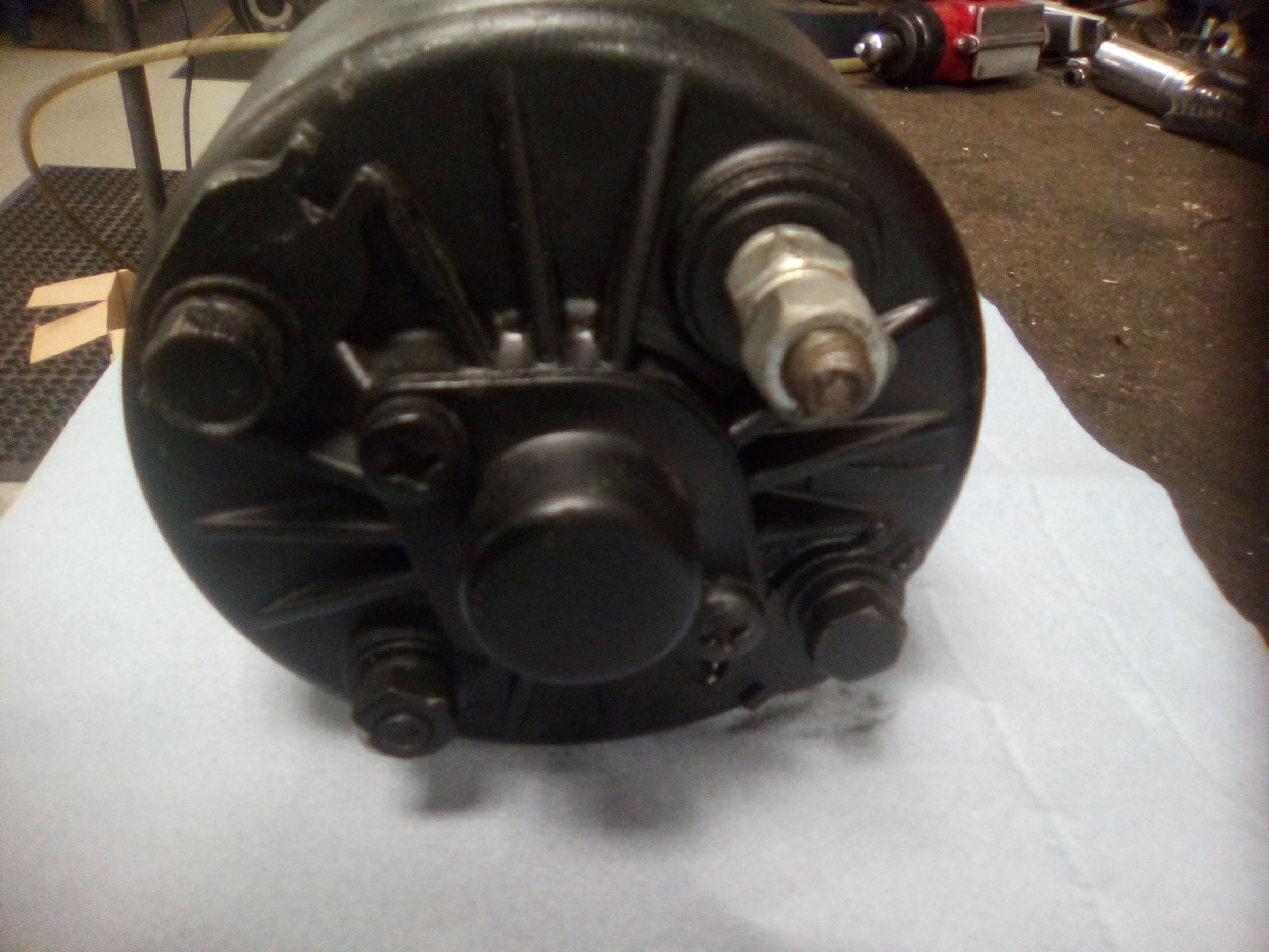
IMG_20200205_092925.jpg

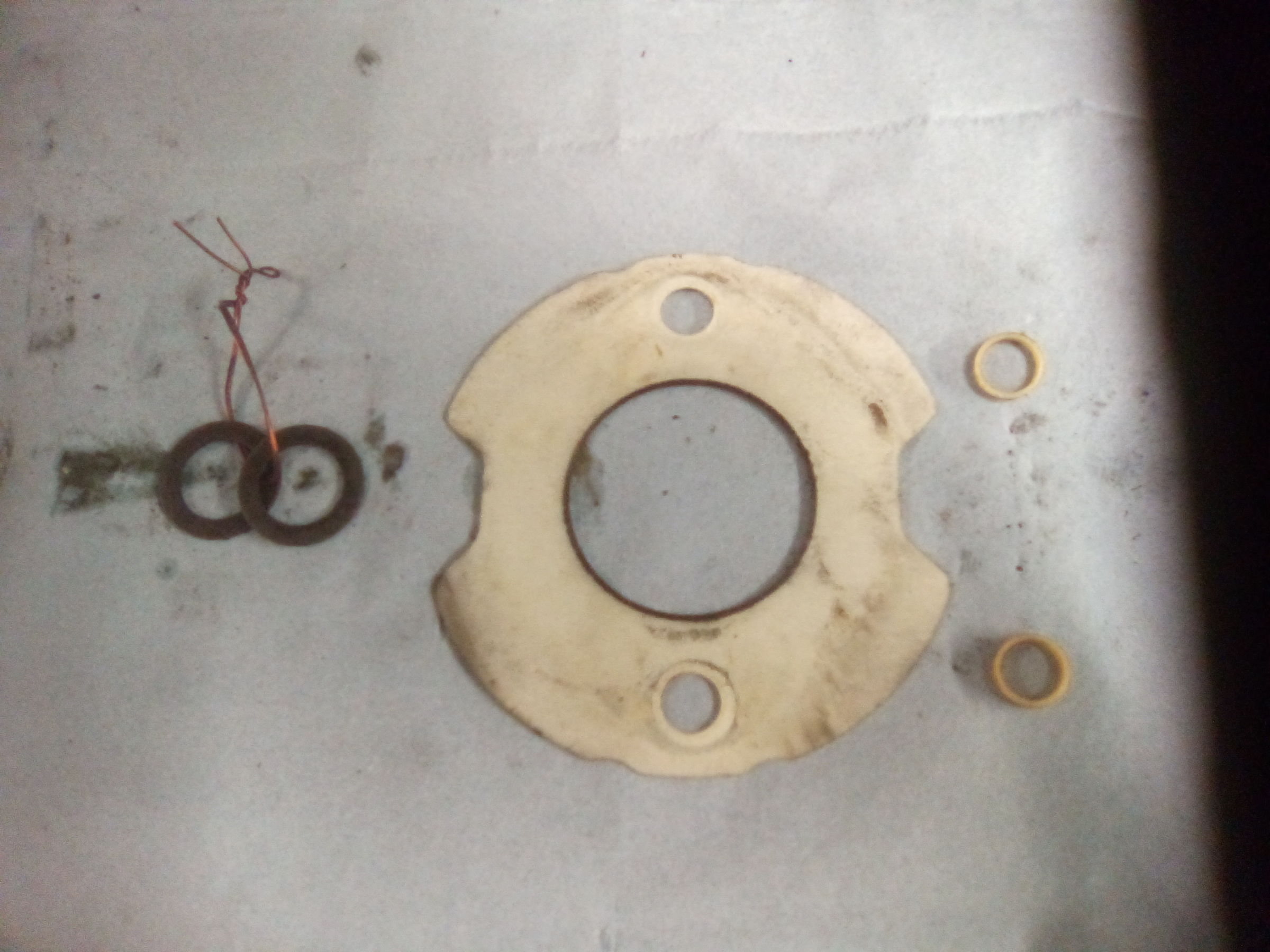
There's also shims to set the end float. I loop a bit of wire through them to keep them together and identify them as being the external group.
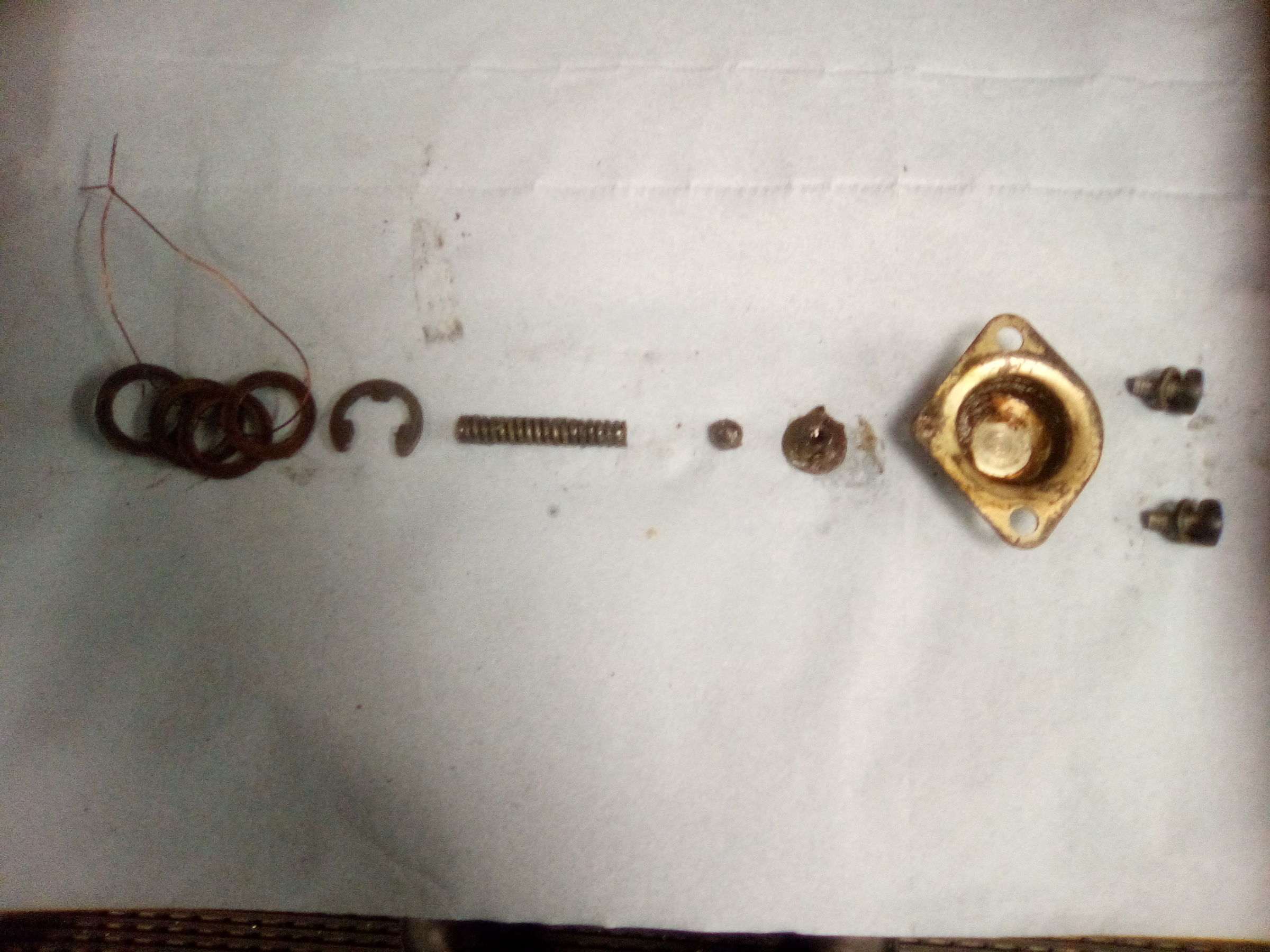
IMG_20200205_093237.jpg
 

snibble

Member
Joined
6 Apr 2020
Messages
35
Visit site
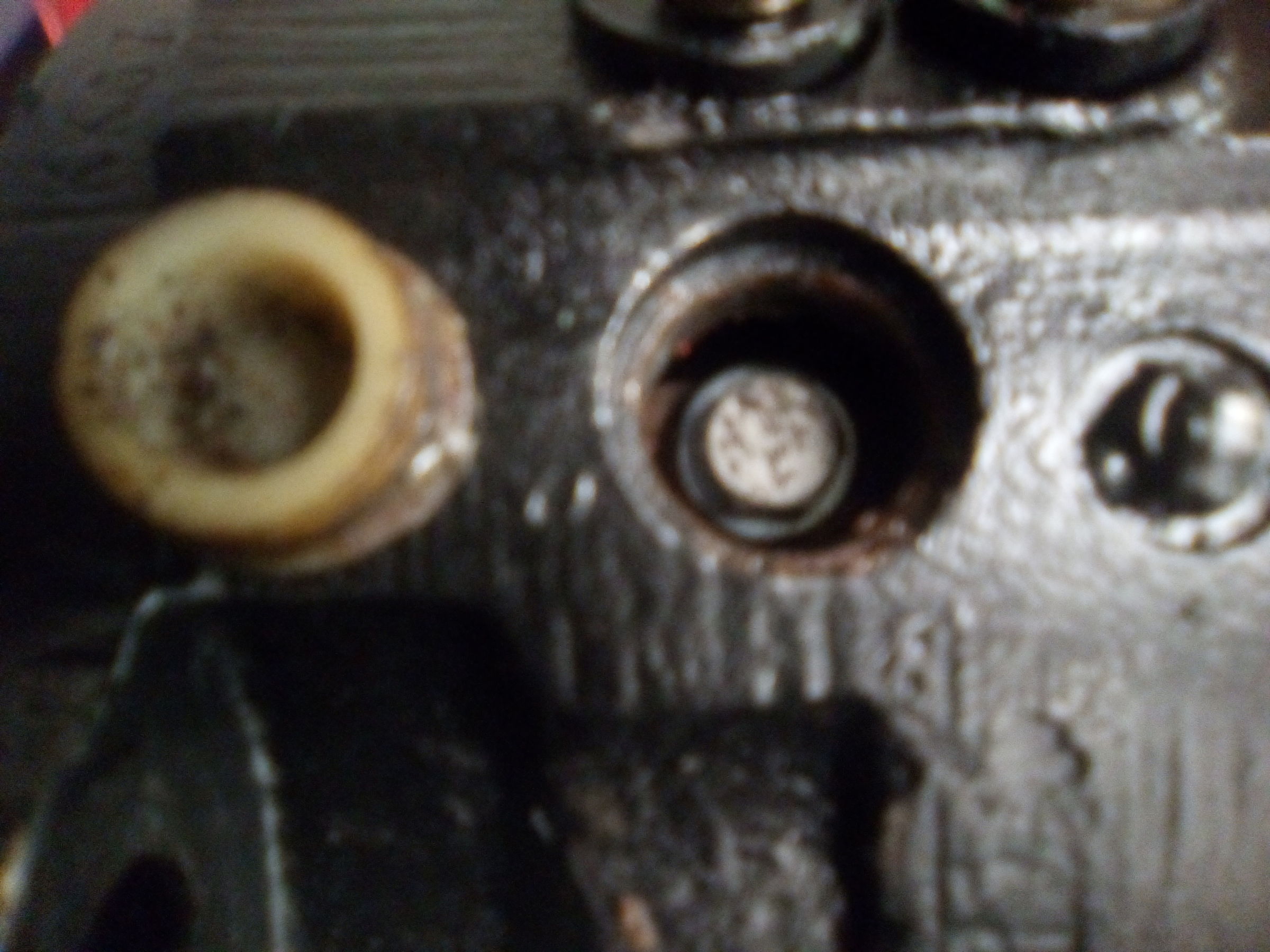
At the front end are two plastic plugs, or steel core plugs.
IMG_20200205_092936.jpg
They have to come out to reveal the field coil connections. This is an S115 starter, that is the metric version of the old CA45 4.5inch starter. Metric, yea right. The threads on these screws are UNC and the hex is 2BA! They have to come out.
IMG_20200205_093355.jpg
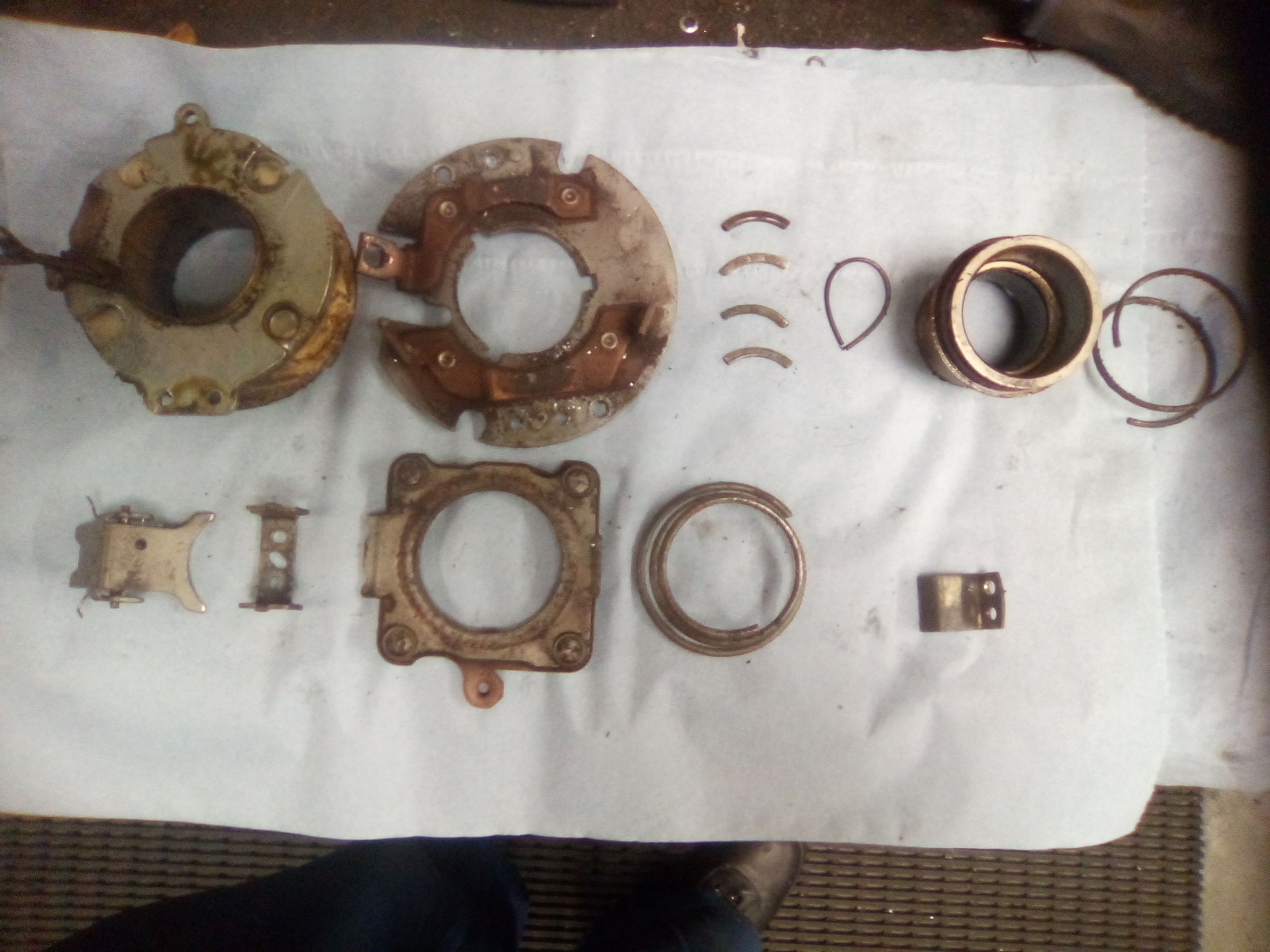
Returning to the back end, the nuts have to come off the negative terminal and the second stud 180° opposite. Then the through bolts and the comm end bracket can be removed. Behind it are these insulators and there SHOULD be O rings as well. Notice the internal group of end float shims which I identify by looping a doubled over length of wire through them.
IMG_20200205_093920.jpg
 

snibble

Member
Joined
6 Apr 2020
Messages
35
Visit site
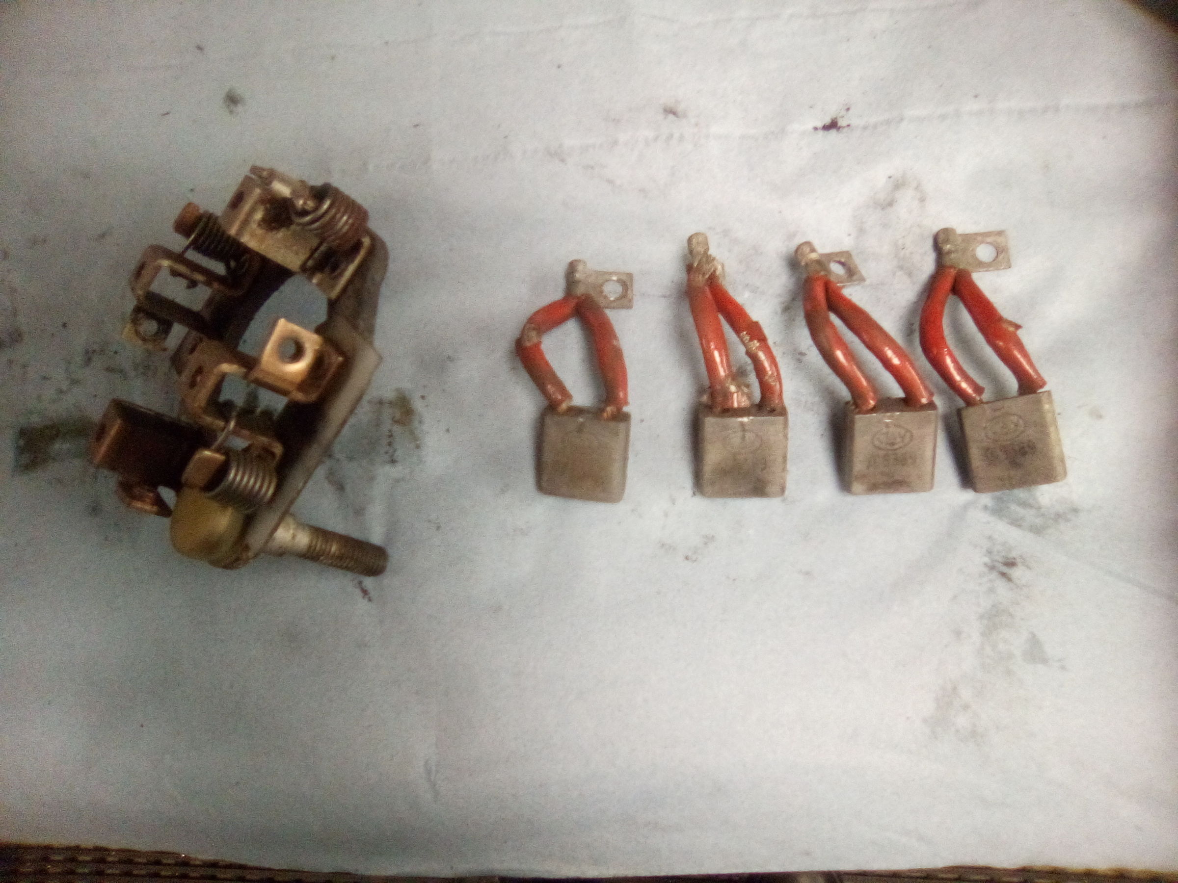
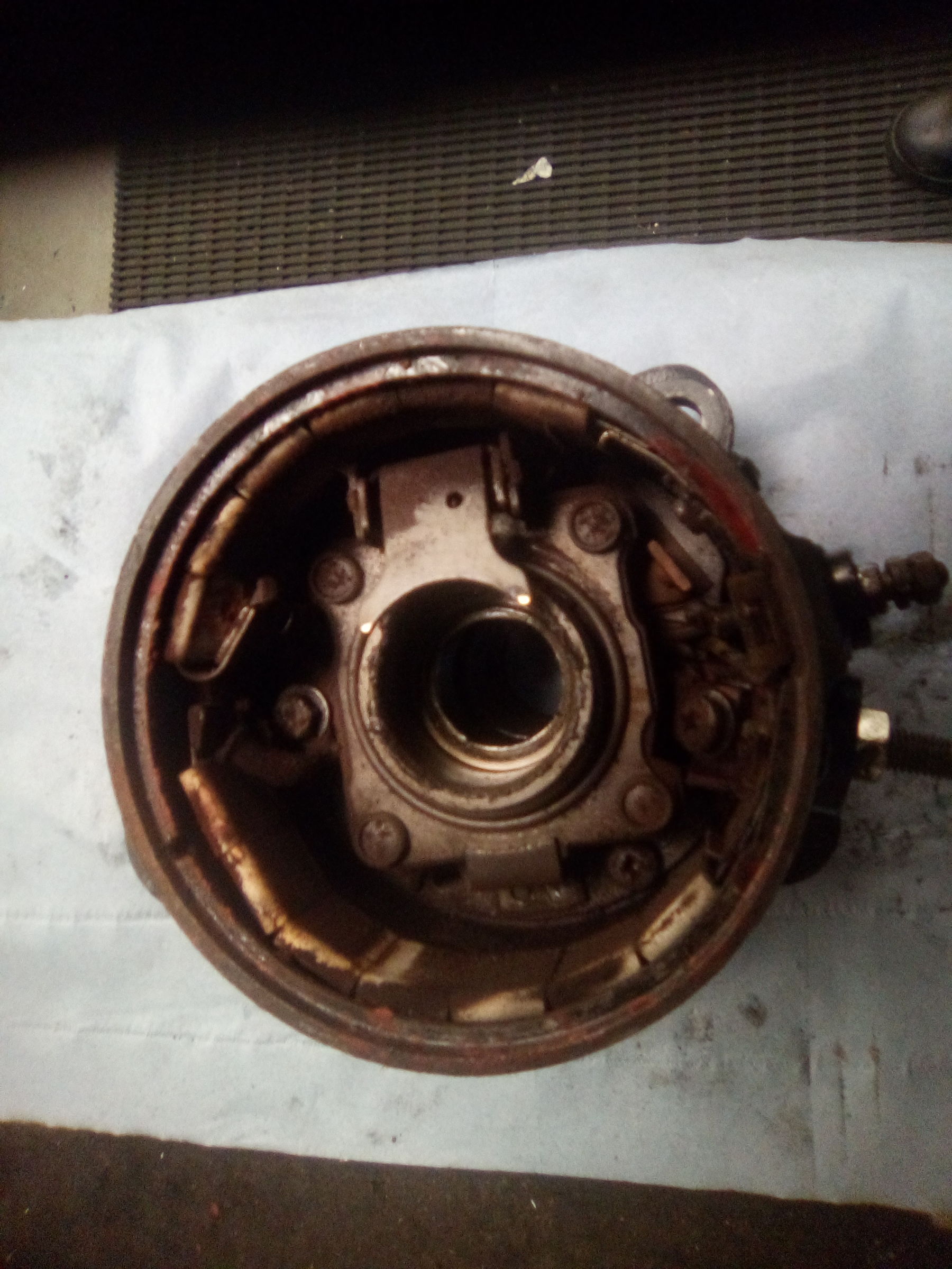
Now the brushes can come out. UNF screws now, and the brush holder can be removed.
IMG_20200205_094338.jpg
And off with the yoke/field coil assembly.
IMG_20200205_094525.jpg
 

snibble

Member
Joined
6 Apr 2020
Messages
35
Visit site
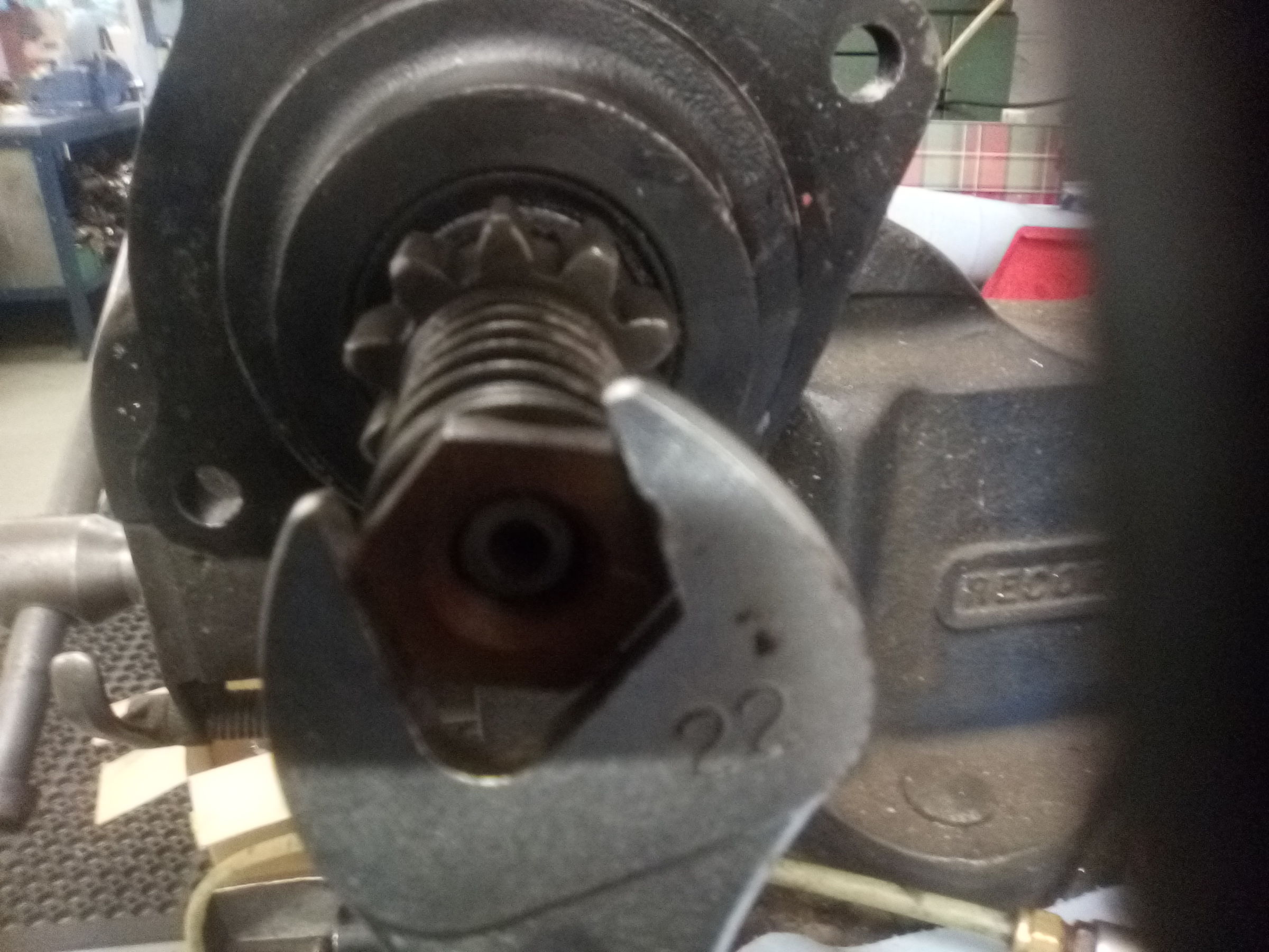
With the armature in the vice (soft jaws) the LEFT HAND THREADED nut can be removed.
IMG_20200205_094634.jpg
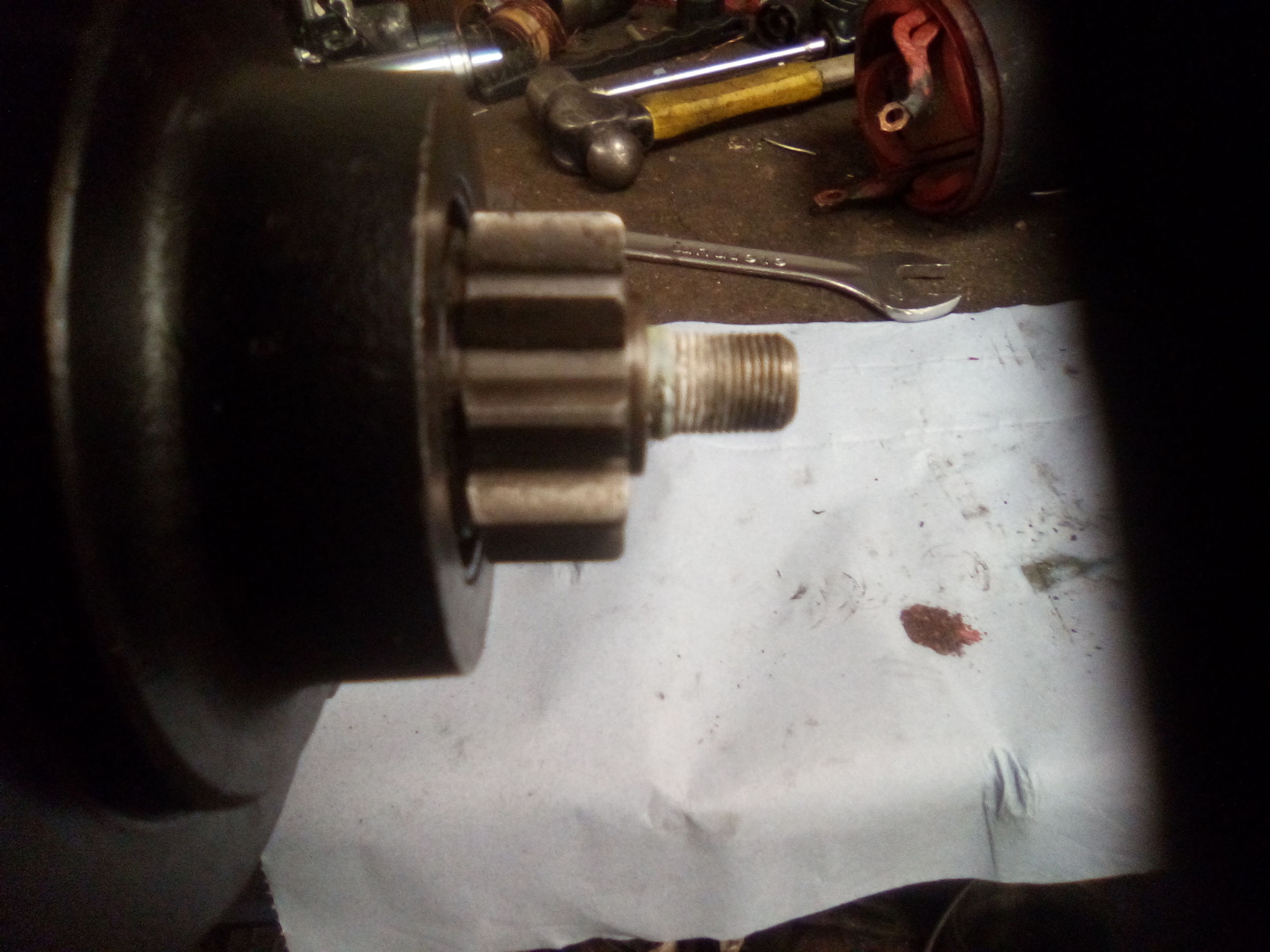
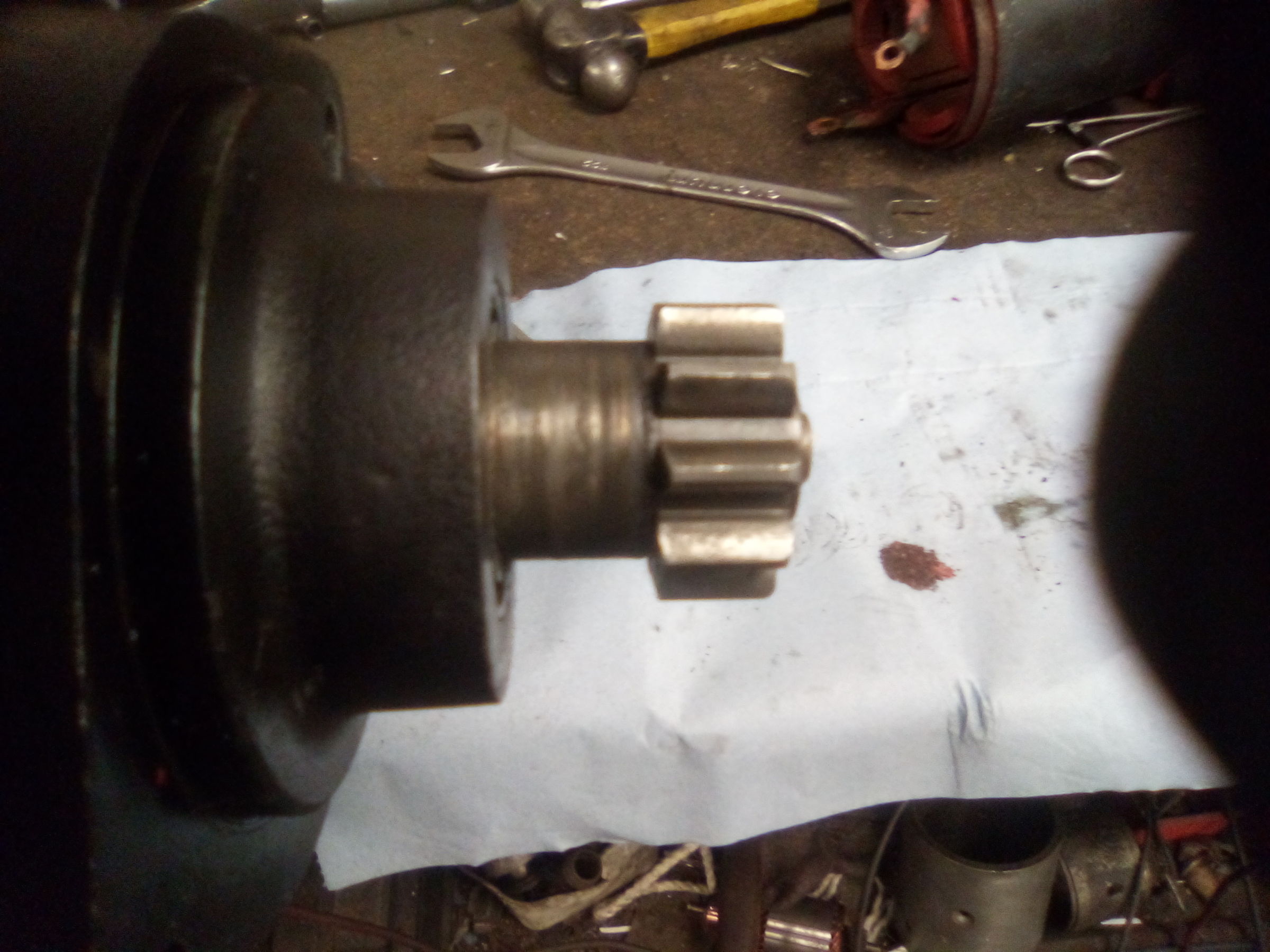
The pinion can be wound up the spiral spline

IMG_20200205_094740.jpg
And with the drive end bracket pushed back
IMG_20200205_094755.jpg
The whole assembly can be withdrawn from the armature, liberating 12 steel balls.
IMG_20200205_094831.jpg
 

snibble

Member
Joined
6 Apr 2020
Messages
35
Visit site
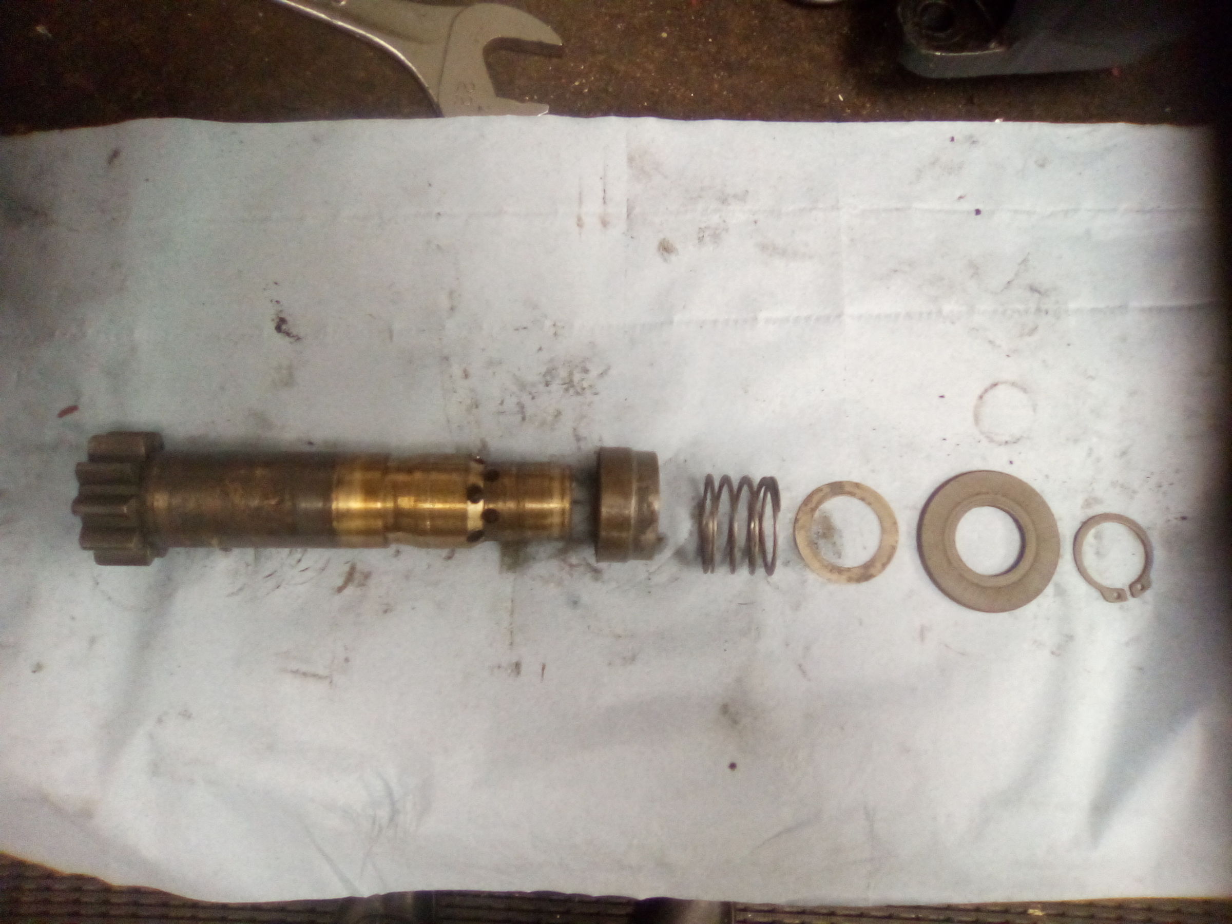
Remove the circlip, trip plate, washer, spring and collar and the pinion can be removed from the solenoid assembly.

IMG_20200205_095220.jpg
Ok. Solenoid assembly. First the resistor has to come out. That's another UNC 2BA screw where it connects to the moving contact and should be two rivets, one at each end. Screws and nuts in this case but all sorts of bodges rear their heads on these things. You can see the resistor around the outside of the casing.
IMG_20200205_095309.jpg
Then the solenoid terminals come out, a screw removed from where the fixed contact joins the positive terminal, two screws holding the assembly in and out it comes.
 

snibble

Member
Joined
6 Apr 2020
Messages
35
Visit site
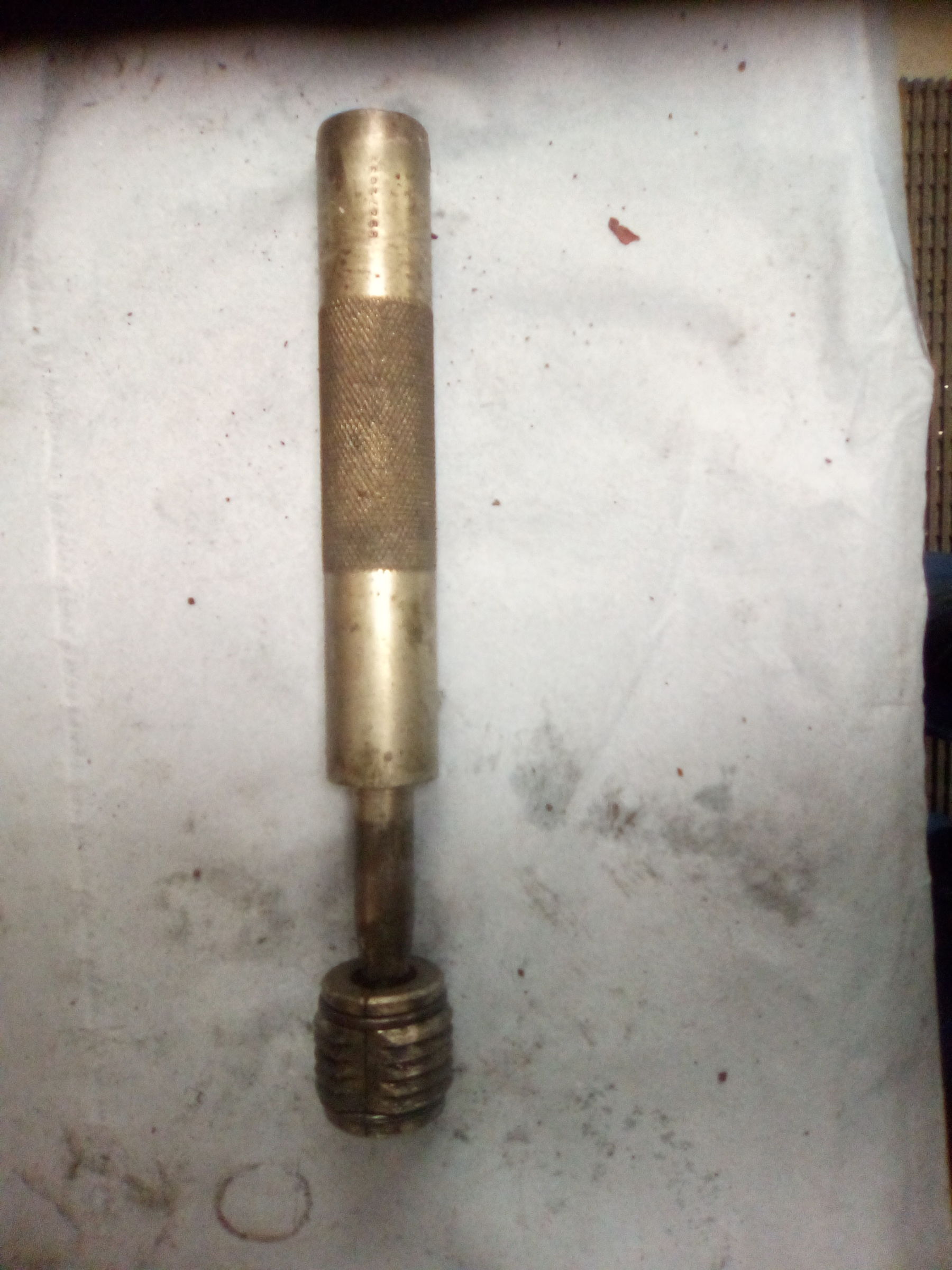
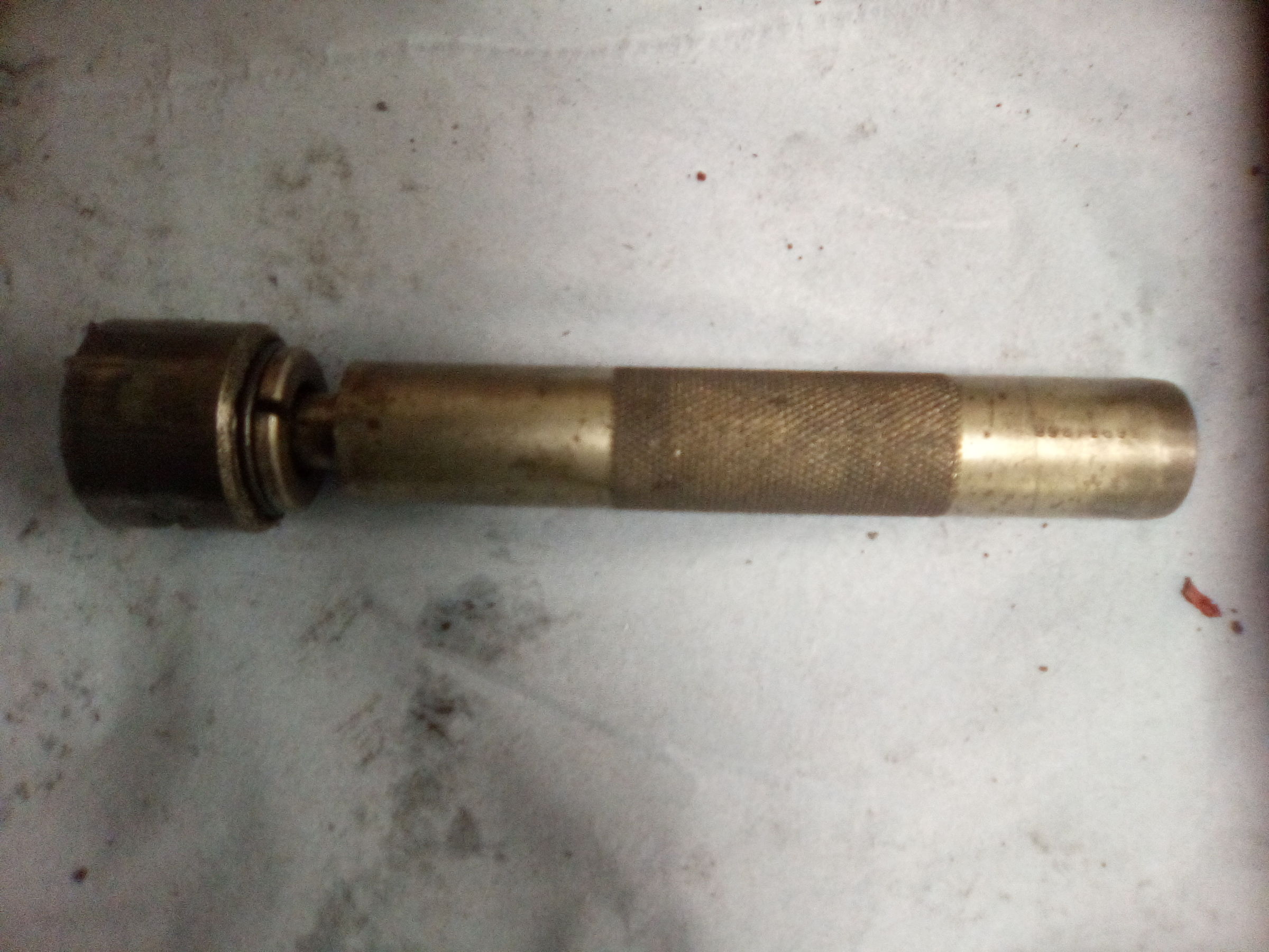
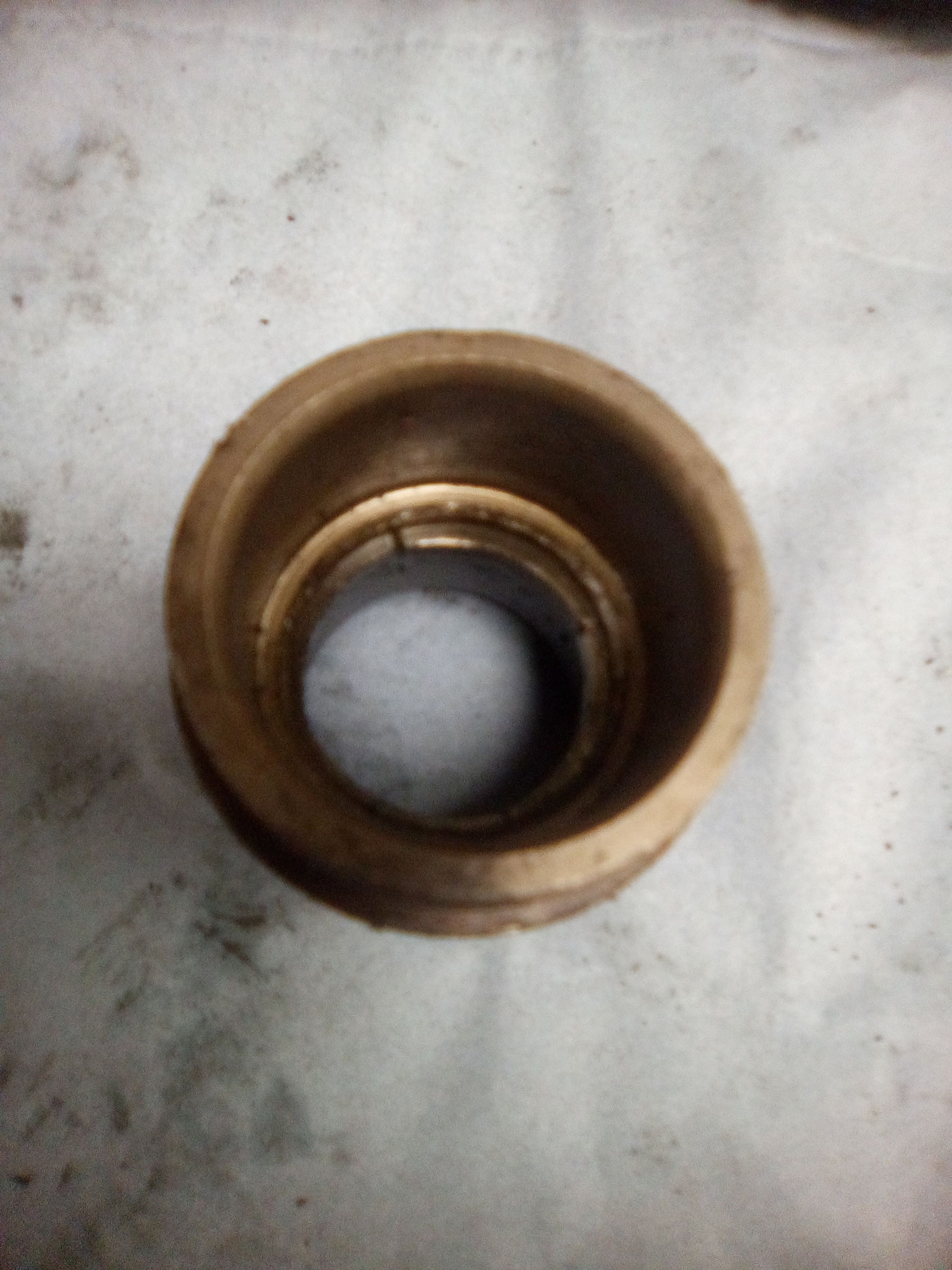
This is the factory tool for removing the drive end bush.
IMG_20200205_103651.jpg
The clawed end goes in like this
IMG_20200205_103910.jpg
Then the shaft section is inserted and you beat it out with a nammer. So it ends up like this.
IMG_20200205_103945.jpg
Without the tool you can put a hacksaw through the bush, cut a slot opposite the one that's already there and collapse the bush to get it out.
IMG_20200205_103520.jpg
To strip the solenoid, the trip lever should be removed, rivets holding the trip lever frame and contact retainer drilled out and the moving contact and plunger withdrawn. The fixed contact plate will now come off and the spring holding the moving contact to the plunger removed to separate them.
 

snibble

Member
Joined
6 Apr 2020
Messages
35
Visit site
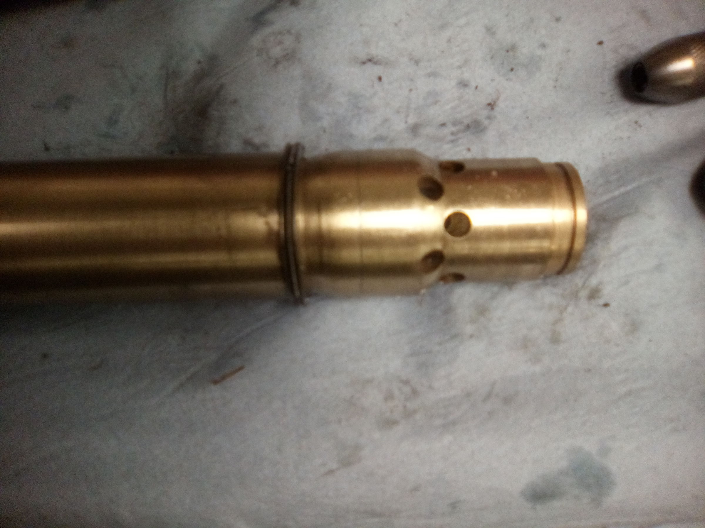
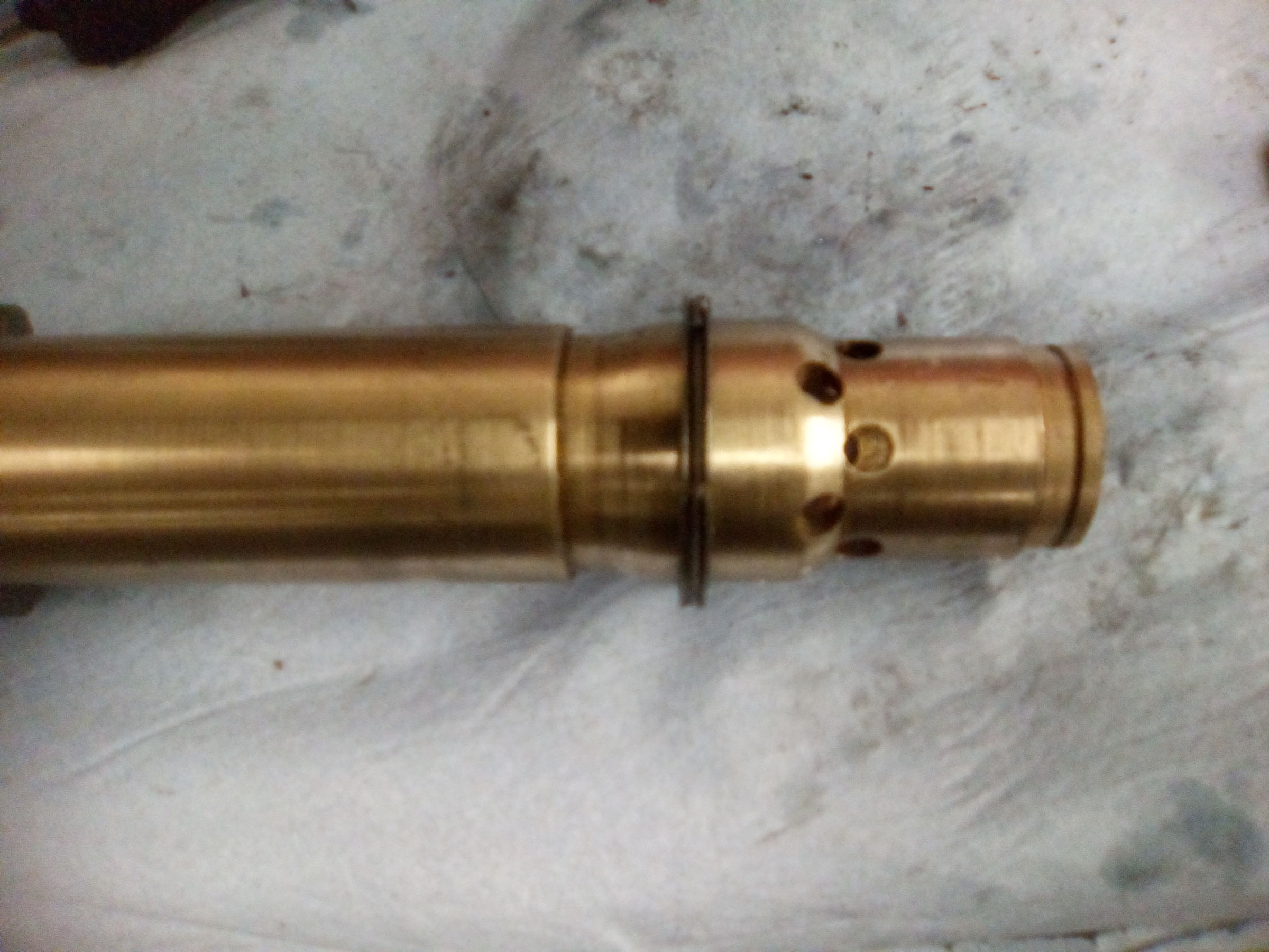
The solenoid plunger has an internal groove which carries four segments held together with a garter spring.
IMG_20200205_104418.jpg
These segments engage a shoulder on the pinion to carry it forward. They come out very easily. If you have the knack of putting them back in then there's nothing to learn in this thread as you must have done it all before. If you don't have that knack and you value your sanity, leave them in!
This is the solenoid stripped down.
IMG_20200205_104850.jpg
 

snibble

Member
Joined
6 Apr 2020
Messages
35
Visit site
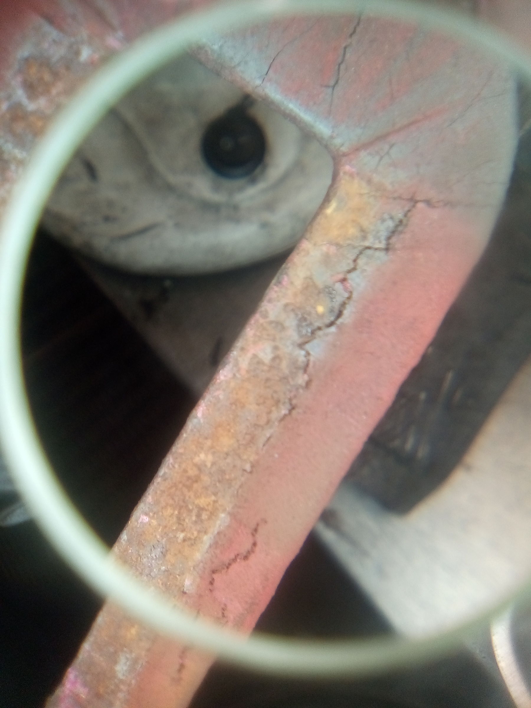
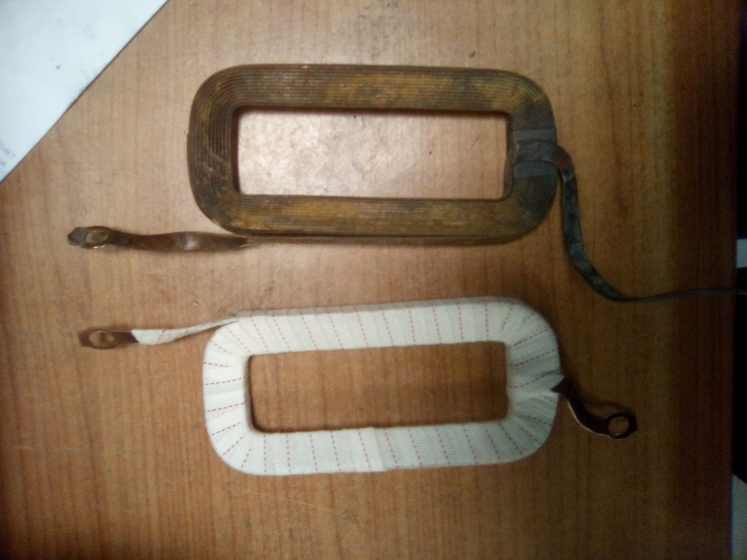
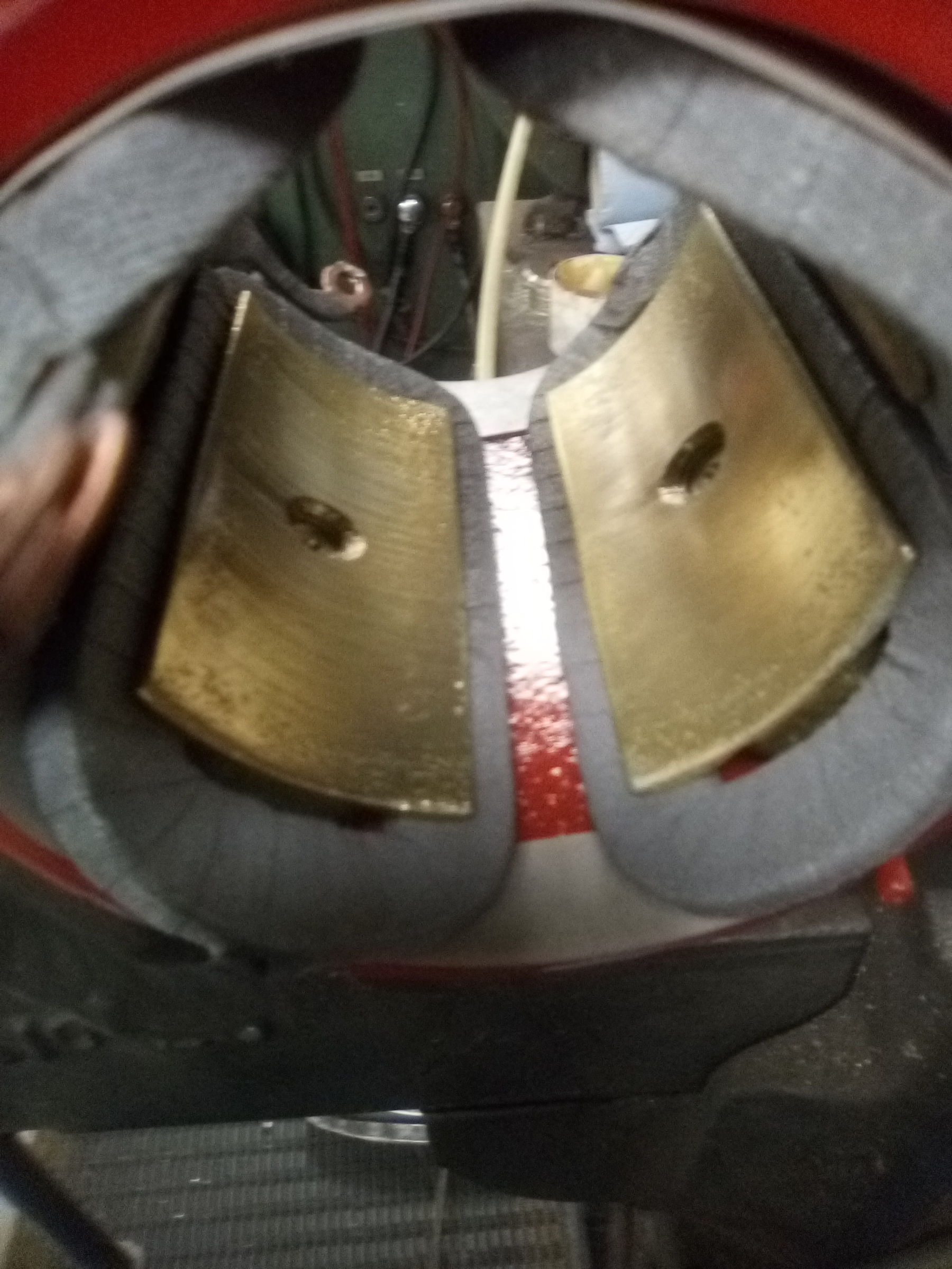
All that's left now is to use a serious impact driver to shift the pole screws and remove the field coils. This coil shows damage typical of the insulation being bitten by expanding rust and they will need to be stripped and re-taped.
IMG_20200205_105700.jpg
One coil stripped, one re-taped. Top tip. You know how raindrops catch on the hairs on a woolly jumper and don't soak in? Well I want the varnish to soak into the fresh tape so I waft a blowlamp flame over it to take the surface fibres off.
IMG_20200205_163930.jpg
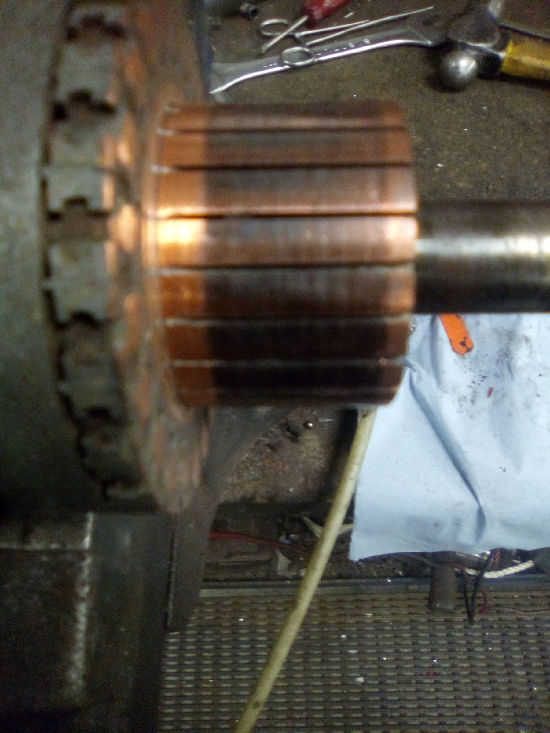
The commutator. The thing to notice here is the colour of the patina. A colour like this is a sure sign of a happy armature.
IMG_20200205_105739.jpg


"Inquest". Why did it fail? This is an important part of the process for me. First off, you get to recognise your own work even years down the line. You also, if you see it often enough recognise other people's work and I'm pretty sure who last saw the inside of this machine. I'm not in the business of badmouthing another blokes work not least because I am fallible too, so I shan't say more on the subject.
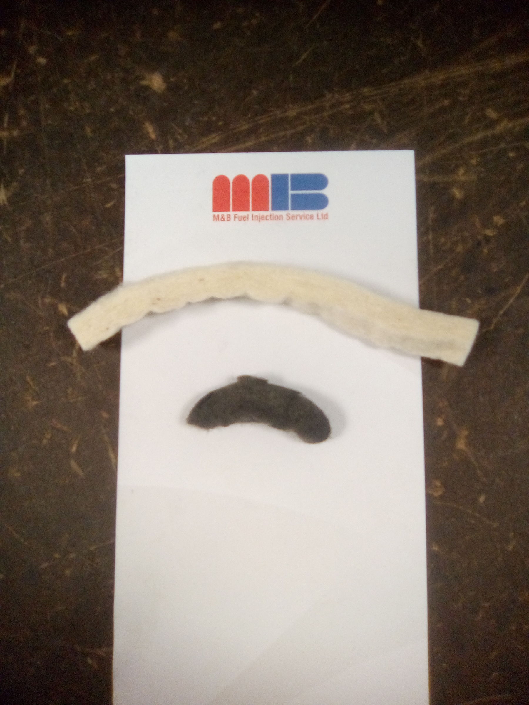
One of the best indicators of what's been going on is the condition of the brushes. In this case wear has not even spread across the full width of the contact surface, the brushes are not yet worn in so failure has been extremely premature. The drive end bush on these is white metal surfaced or more recently bronze. It should be lubricated by an oil soaked wick held in contact with the pinion by a spring. The spring was absent and only a small fragment of wick fitted. In consequence the pinion has picked up on the bush and was smeared with white metal. The bush is worn out and the armature has been in contact with the field pole shoes. There is extensive rust partly because the field coils weren't removed just the whole assembly sprayed over. Surface treatments on some components has been removed by buffing on a wire wheel and sealing O rings left out. In short, failure is due to sub standard overhaul. Shame on you matey!

To give this some context. A new starter from the manufacturer is £1,214.58. A cheap exchange unit (at this point I'm staring at the ceiling whistling) about £300. Both these prices are ex vat.
 

snibble

Member
Joined
6 Apr 2020
Messages
35
Visit site
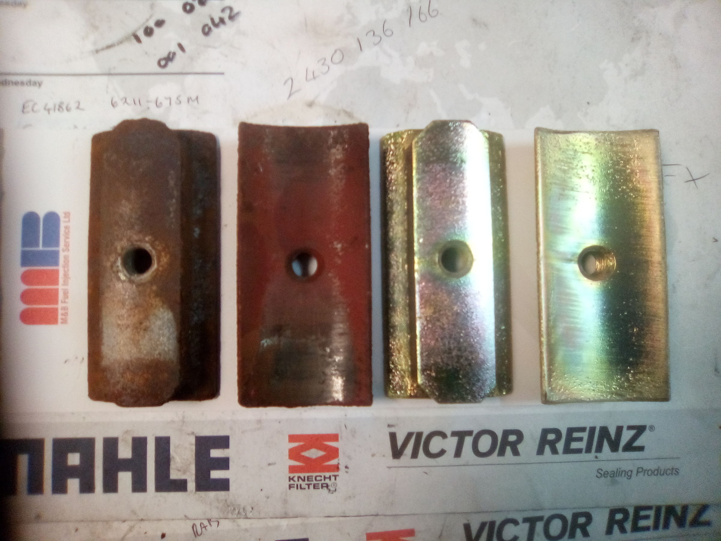
Field pole shoes. Two showing untreated rust and damage from armature rubbing. Two cleaned up with a coat of zinc plating flashed over them. This is a marine unit off a saltwater boat. Corrosion isn't defeated with a wire brush and wishful thinking.
IMG_20200206_113243.jpg
Yoke/field coil assembly ready.
IMG_20200206_163846.jpg

New lubricator wick and the fragment fitted.
1581080461857145963222078727304.jpg

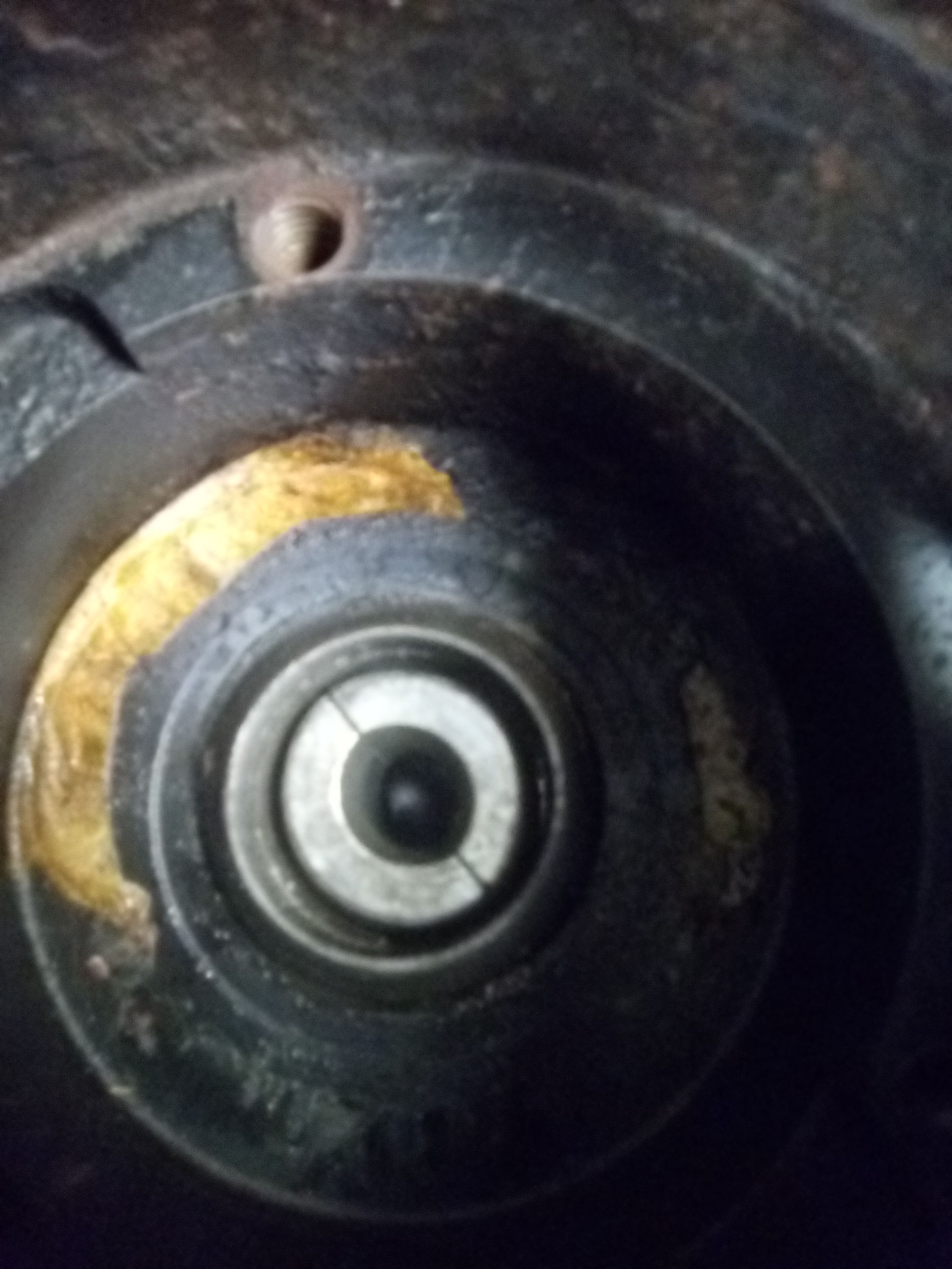
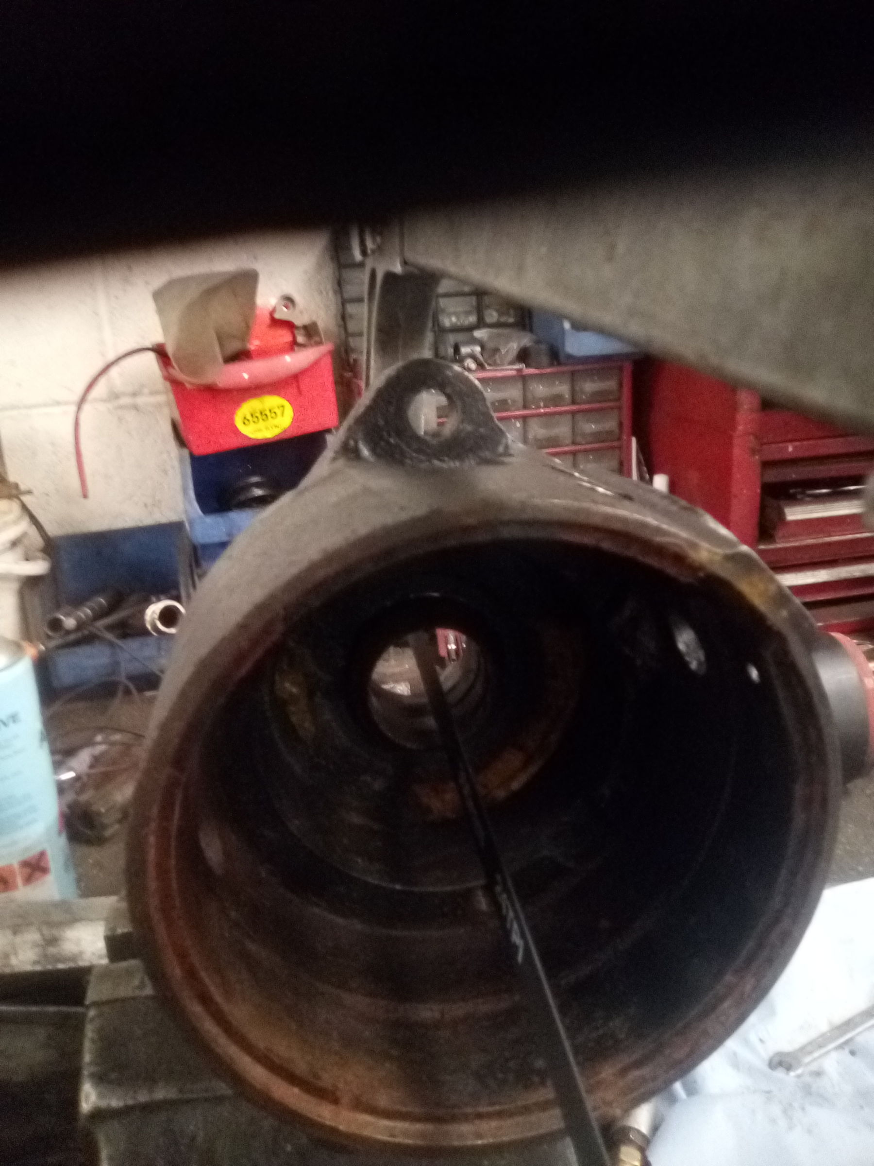
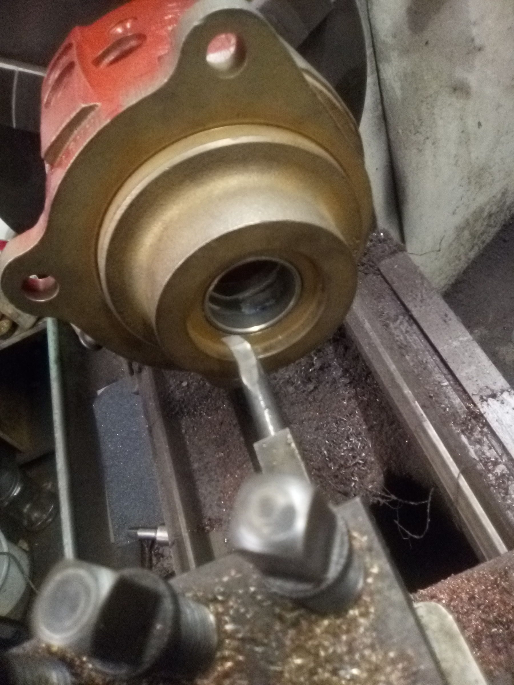
Bush pressed in, now it must be bored to suit the pinion, lubricator aperture filled with a bit of card to keep swarf out.
15810859674402005998533166765073.jpg
 

snibble

Member
Joined
6 Apr 2020
Messages
35
Visit site
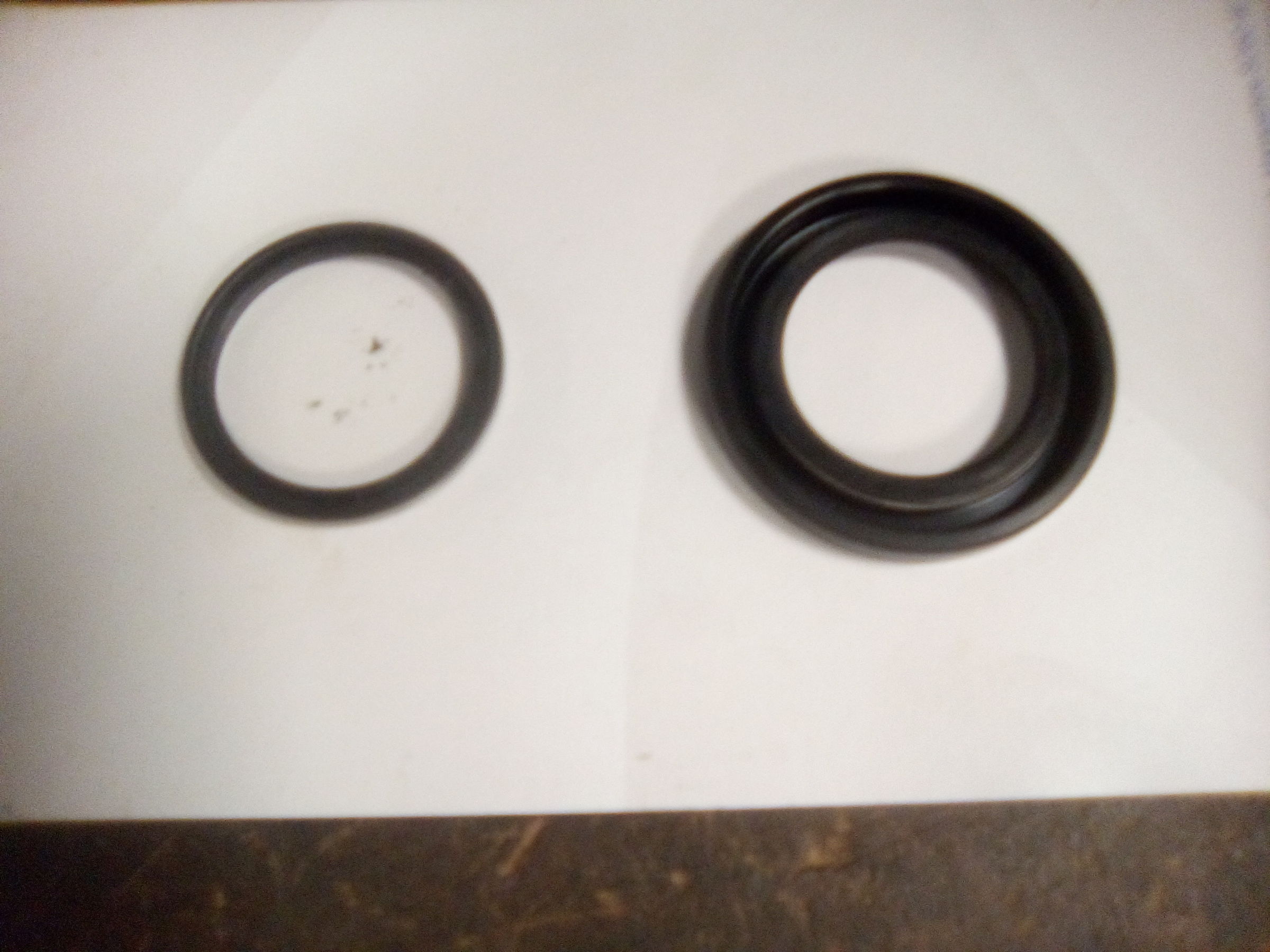
Seals. I'm using genuine parts from prestolite, the inheritors of the CAV brand. The seal on the left is a dust seal that comes with the repair kit. The one on the right is going in this unit which means I get to keep the other one. Unfortunately, the ones supplied these days are too tight and inflexible and restrict the movement of the pinion to the point where the starter won't engage! Fortunately I have a drawer full of good ones left over from years of saving them.
IMG_20200207_150404.jpg
A rant.
O rings left out. No no no. Absolutely not acceptable. O rings are not difficult to get in whatever size. They come under the heading of basic engineering supplies. No excuse. The missing spring. Same again. It's an important part as shown by it's omission resulting in accelerated wear and premature failure. Not being able to get it with A CAV part number on it is again no excuse. I use springs that differ from the original by 0.3mm in the outside diameter. They're brush springs for a French starter and I buy them in packs of ten. It just takes a little effort and a reasonable pride in your work.
Rant over.
Right, how it works. First the excuses. It's difficult taking useful video with one hand whilst functioning metalwork with the other. I've done my best.
Electrically it's dead simple. Three contacts. First contact connected to battery +ve. Second contact to the motor. Moving contact has its own connection to a bloody great resistor and thence to the motor, and also forms a bridge from first to second contact.
Initial contact is on the right of the picture. Remember the solenoid plunger is carrying the pinion forward into mesh with the flywheel. First contact made current flows into the moving contact, through the resistor and to the motor which rotates slowly. This rotation ensures smooth engagement and with the pinion held by the flywheel, the spiral spline winds it forward into full engagement. A disc on the rear of the pinion trips a lever which releases the left side of the moving contact and it snaps down to the second contact, bypassing the resistor and supplying full power to the motor, cranks the engine. A picture is worth a thousand words.
 

snibble

Member
Joined
6 Apr 2020
Messages
35
Visit site
<div style="width:100%;height:0px;position:relative;padding-bottom:75.000%;"><iframe src="solenoid - Streamable" frameborder="0" width="100%" height="100%" allowfullscreen style="width:100%;height:100%;position:absolute;left:0px;top:0px;overflow:hidden;"></iframe></div>
 

snibble

Member
Joined
6 Apr 2020
Messages
35
Visit site
Diesel engines, as we have all seen, can tend to cough and fart a bit before becoming self sustaining and if every half hearted semi combustion of under heated fuel were to kick the pinion back down the spiral spline out of mesh, then on a cold day you'd never get the thing started. So there has to be some means of locking it in the engaged position. This picture illustrates two things. The four segments held by their garter spring in contact with the shoulder that carries the pinion forward and more pertinent here, two rows of holes which accept small steel balls. the row nearest the non drive end is what we are concerned with at the moment.

IMG_20200207_091829.jpg
 

snibble

Member
Joined
6 Apr 2020
Messages
35
Visit site
As the pinion moves into engagement the balls drop into recesses in the armature and a spring loaded collar snaps forward over then to hold them in place and the pinion is locked in the engaged position.
<div style="width:100%;height:0px;position:relative;padding-bottom:75.000%;"><iframe src="engagement - Streamable" frameborder="0" width="100%" height="100%" allowfullscreen style="width:100%;height:100%;position:absolute;left:0px;top:0px;overflow:hidden;"></iframe></div>
 

snibble

Member
Joined
6 Apr 2020
Messages
35
Visit site
When the starter button is released the solenoid plunger, in moving back, pushes the collar clear of the steel balls and they ramp out of the recesses in the armature and the pinion is released to return to the at rest position.
<div style="width:100%;height:0px;position:relative;padding-bottom:75.000%;"><iframe src="disengage - Streamable" frameborder="0" width="100%" height="100%" allowfullscreen style="width:100%;height:100%;position:absolute;left:0px;top:0px;overflow:hidden;"></iframe></div>
 

snibble

Member
Joined
6 Apr 2020
Messages
35
Visit site
Overspeed. In this picture it can be seen that as the motor torque working through the spiral spline takes over from the solenoid to complete engagement, the four segments that drove the pinion forward initially, ride up the slope on the pinion and expand into their groove where they are held by the solenoids magnetic field. With these segments clear of the pinion there are only the locking balls preventing the engine driving the pinion out of mesh.
IMG_20200207_091852.jpg
Now the spring loaded sleeve that retains the locking balls in place. Notice the internal ramp.
IMG_20200207_092101.jpg
 

snibble

Member
Joined
6 Apr 2020
Messages
35
Visit site
The second row of balls are no more than centrifugal weights. Under overspeed conditions they impinge on the ramp to slide the sleeve back and free the locking balls allowing the engine to spin the pinion back out of mesh.
<div style="width:100%;height:0px;position:relative;padding-bottom:75.000%;"><iframe src="overspeed - Streamable" frameborder="0" width="100%" height="100%" allowfullscreen style="width:100%;height:100%;position:absolute;left:0px;top:0px;overflow:hidden;"></iframe></div>
 

snibble

Member
Joined
6 Apr 2020
Messages
35
Visit site
And that's it. Electrically simple, mechanically complex.
The hissing noise in the videos by the way, we don't have a leaky air system, it's an ultrasound cleaning tank.
Now you know why the British worker has productivity problems, he's busy illustrating the job for boaters.
 

snibble

Member
Joined
6 Apr 2020
Messages
35
Visit site
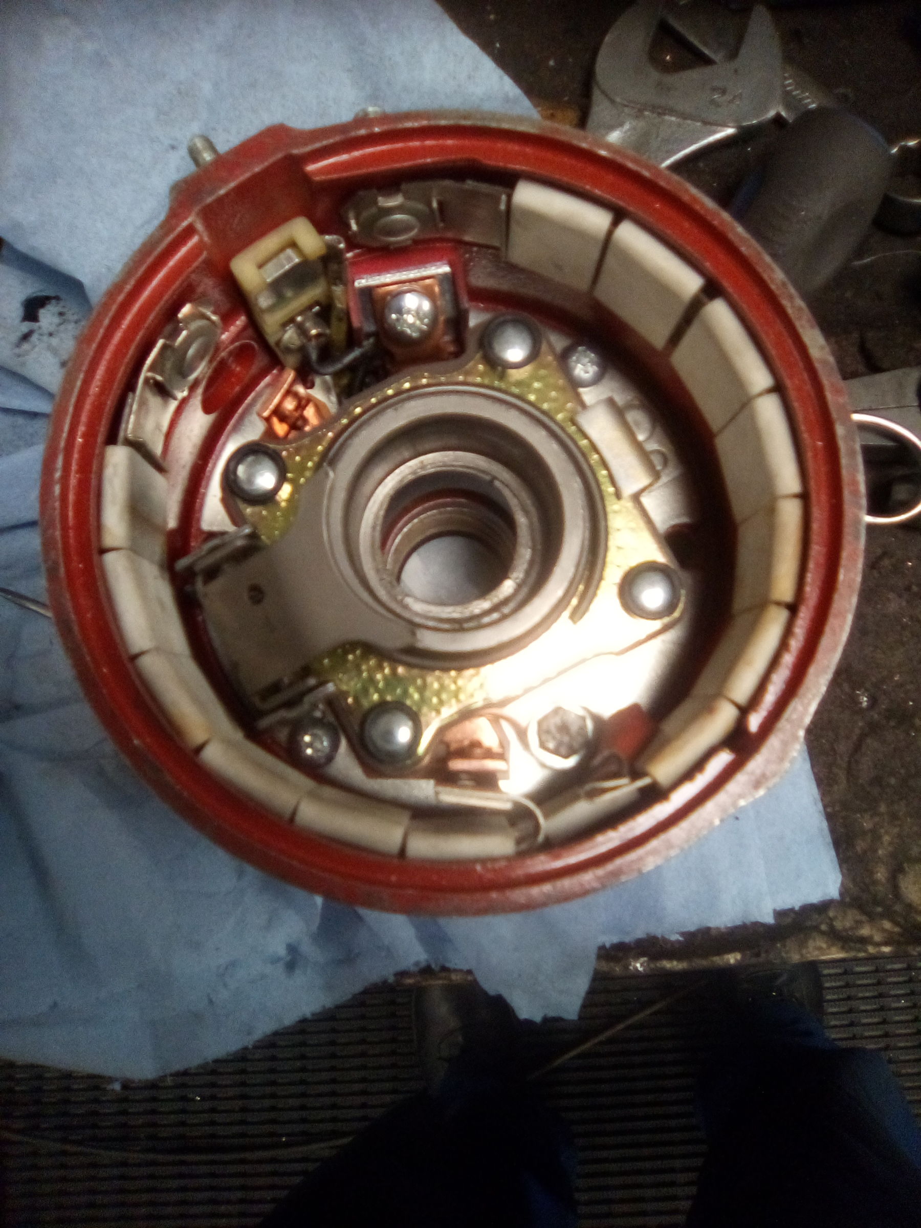
All the complicated stuff assembled. The resistor is visible around the circumference, highlighted by the white ceramic insulators. Connection to the moving contact at 5 o'clock, from resistor to second contact (motor) at 6 o'clock.
IMG_20200210_081050.jpg
 

snibble

Member
Joined
6 Apr 2020
Messages
35
Visit site
I've decided not to do a test in the vice as doing it one handed whilst filming with the other just runs too high a risk of metal mingling with flesh. So, to the test bench and brake test.
<div style="width:100%;height:0px;position:relative;padding-bottom:75.000%;"><iframe src="test - Streamable" frameborder="0" width="100%" height="100%" allowfullscreen style="width:100%;height:100%;position:absolute;left:0px;top:0px;overflow:hidden;"></iframe></div>
 
Top