You are using an out of date browser. It may not display this or other websites correctly.
You should upgrade or use an alternative browser.
You should upgrade or use an alternative browser.
Wiring
- Thread starter PabloPicasso
- Start date
LittleSister
Well-Known Member
Can't see your diagram.
PabloPicasso
Well-Known Member
Hmmm, don't know why, its showing in my browser.Can't see your diagram.
I'll post it again.
Attachments
PaulRainbow
Well-Known Member
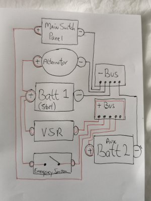
I can see the picture. I don't see any isolator switches or fuses. The emergency switch should be between the load terminals of the isolators, not the batteries.I'm intending to improve the posituins and witing of my two LA battery system.
Please have a look at my diagram and see if itnreoresenta a good plan. Is there anything obvious that I've missed
Many thanks
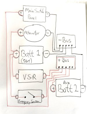
Try this :

PabloPicasso
Well-Known Member
That's a useful schematic.
Yes there are isolator keys, but I've neglected to draw them in.
Also, all the electronics are fused at the main panel. Again, I didn't draw them in.
Easiest place for a combien/emergency power to start would be between the isolator keys as you show.
Very helpful, many thanks.
Yes there are isolator keys, but I've neglected to draw them in.
Also, all the electronics are fused at the main panel. Again, I didn't draw them in.
Easiest place for a combien/emergency power to start would be between the isolator keys as you show.
Very helpful, many thanks.
Last edited:
Oily Rag
Well-Known Member
Thank you Paul Rainbow for the diagram.
I don’t have a shunt in my system at present and simply monitor battery state with a voltmeter in the morning while the kettle boils (on gas!)
If I decide to add a shunt as per the diagram, it would have to be able take the current when the Emergency Combine switch is closed. Is there any specification or part number I could look at? (2x100Ah domestic and 1x100Ah for engine normal start. 30 hp diesel engine. )
Many thanks.
PaulRainbow
Well-Known Member
A Victron Smartshunt, available in 300A or 500A, 300A should work well for you.Thank you Paul Rainbow for the diagram.
I don’t have a shunt in my system at present and simply monitor battery state with a voltmeter in the morning while the kettle boils (on gas!)
If I decide to add a shunt as per the diagram, it would have to be able take the current when the Emergency Combine switch is closed. Is there any specification or part number I could look at? (2x100Ah domestic and 1x100Ah for engine normal start. 30 hp diesel engine. )
Many thanks.
Aurai
Well-Known Member
Do we just assume negative bus is often a stud on your engine? As my 3 pot Yanmar, has such a stud. Or do you run from bus to engine stud? Thanks
PaulRainbow
Well-Known Member
Isn't this clear from the schematic in post #4 ?Do we just assume negative bus is often a stud on your engine? As my 3 pot Yanmar, has such a stud. Or do you run from bus to engine stud? Thanks
Aurai
Well-Known Member
Hi Paul, I was sort of asking. Not immediately obvious to me, I can see the cable to the shunt and onto/from bus bar. But did not take that to be a stud on the engine. Hence trying to relate it to my own set up. As ever, I like to keep up and learn. Thanks
PaulRainbow
Well-Known Member
Fair enough. Not familiar with your exact setup, but you'll have a negative battery cable going somewhere, probably to the stud you mention. In the schematic above you would take that battery cable to the busbar then a cable from the busbar to the engine stud. Any additional wires on the stud, that go somewhere on the engine can stay put.Hi Paul, I was sort of asking. Not immediately obvious to me, I can see the cable to the shunt and onto/from bus bar. But did not take that to be a stud on the engine. Hence trying to relate it to my own set up. As ever, I like to keep up and learn. Thanks
The negative going to the starter motor in the schematic is somewhat generic, it may in fact go to the starter or somewhere on the engine block, no matter where it currently goes, the other end of it goes to the busbar. The point of the busbar connections are so that the alternator charging (to the domestic bank only) goes through the shunt and the current going to the domestic bank is "seen" by the battery monitor.
Last edited: