You are using an out of date browser. It may not display this or other websites correctly.
You should upgrade or use an alternative browser.
You should upgrade or use an alternative browser.
wireing question
- Thread starter chrishelen
- Start date
VicS
Well-Known Member
Sorry still no wiser.
Which terminal on the ignition switch, what else is on the same terminal.
I think you should start with a clean sheet of paper and design the electrical system to do what you want it to do.
If that involves a split charge relay then maybe this is it...... but you still have not told us what identifying numbers, if any, there are on it
chrishelen
N/A

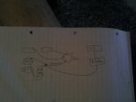
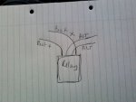
OK hope this makes sense,the wire I thought went to the ignition switch powers the breaker box, the common lead from the 1-2 both joins a cable from the starter, where these cables join is where the relay switch gets its power, could I take the cable from the breaker box andconect it to the 3 way common lead, and then connect the other two cables from the relay up to the starter where the common connects.
VicS
Well-Known Member
View attachment 42165
OK hope this makes sense,the wire I thought went to the ignition switch powers the breaker box, the common lead from the 1-2 both joins a cable from the starter, where these cables join is where the relay switch gets its power, could I take the cable from the breaker box andconect it to the 3 way common lead, and then connect the other two cables from the relay up to the starter where the common connects.
If I have understood you properly and you connect it as you have shown in the diagram.
ie two thin wires to the alternator One thickish to one end or the other of the cable between switch and starter the other thickish one to the "breaker box" there will probably only be power to the "breaker box" when the engine is running.
Is this what you want ??????
Last edited:
VicS
Well-Known Member
I strongly recommend that you read the "Boat electrical notes" on Tony Brooks' TB-Training website
http://www.tb-training.co.uk/
http://www.tb-training.co.uk/
chrishelen
N/A
I strongly recommend that you read the "Boat electrical notes" on Tony Brooks' TB-Training website
http://www.tb-training.co.uk/
You are right Vic, thanks for the link.
chrishelen
N/A
Just re read your post Vic, there will be power to the breaker box, and the switch panel, that's OK, isn't it?
VicS
Well-Known Member
Just re read your post Vic, there will be power to the breaker box, and the switch panel, that's OK, isn't it?
You dont show any power to the "breaker box" other than via this relay.
prv
Well-Known Member
You dont show any power to the "breaker box" other than via this relay.
I think the squashed spider to the left of the word "common" is meant to represent all the wires being connected together. This means the breaker panel is powered from the common terminal as it should be, and also that the relay is doing nothing at all - but the latter at least does match what was described in the OP.
Pete
Last edited:
JumbleDuck
Well-Known Member
This is how a 1,2, both,off switch should be wired ( two batteries here making up the domestic bank)
As a matter of interest, what's the rationale for taking +ve and -ve from different batteries in the house bank? Is it so that drops in the interconnects leave both batteries at the same voltage?
VicS
Well-Known Member
As a matter of interest, what's the rationale for taking +ve and -ve from different batteries in the house bank? Is it so that drops in the interconnects leave both batteries at the same voltage?
Yes basically so that small differences in the resistance of the wiring dont cause unequal loading and charging of the batteries in a bank. Can get very complicated with more batteries.
Al explained at http://www.smartgauge.co.uk/batt_con.html
Lots of other useful info in the technical section of the Smartgauge website
chrishelen
N/A
I think the squashed spider to the left of the word "common" is meant to represent all the wires being connected together. This means the breaker panel is powered from the common terminal as it should be, and also that the relay is doing nothing at all - but the latter at least does match what was described in the OP.
Pete
So I am on the right track Pete? What to do with the small wires going to the alt from the relay? + ve,- ve they must be.
prv
Well-Known Member
So I am on the right track Pete? What to do with the small wires going to the alt from the relay? + ve,- ve they must be.
If both the large wires from the relay are connected to the same point then it is doing precisely nothing. In that case, what to do with the small wires is the same as the large wires and the relay itself - stick it all in the bin!
Pete
chrishelen
N/A
Yes they both come off the common to feed the relay.
VicS
Well-Known Member
I think the squashed spider to the left of the word "common" is meant to represent all the wires being connected together. This means the breaker panel is powered from the common terminal as it should be, and also that the relay is doing nothing at all - but the latter at least does match what was described in the OP.
Pete
If so back to square one. Nothing makes much sense to me.
Not enough info to understand what the present set up might have been supposed to do and insufficient info from the OP describing what he wants to achieve to design a new system other than to suggest that my circuit in #4 offers a simple, workable, manual system without a relay.
chrishelen
N/A
That's what I have used, just wasn't sure of what to do with the relay.If so back to square one. Nothing makes much sense to me.
Not enough info to understand what the present set up might have been supposed to do and insufficient info from the OP describing what he wants to achieve to design a new system other than to suggest that my circuit in #4 offers a simple, workable, manual system without a relay.
prv
Well-Known Member
That's what I have used, just wasn't sure of what to do with the relay.
Why do you want to do anything with it?
Pete
VicS
Well-Known Member
That's what I have used, just wasn't sure of what to do with the relay.
As you have described it and how Pete interprets your diagram its not doing anything anyway so disconnect it and remove it ...... but keep a note of how it was connected just in case.
The alternative perhaps would be to use the selector switch as a "use" selector only, taking the alternator output to one battery and using the relay as a battery combining relay to parallel the batteries and charge both while the engine is running.
Some circuits in links posted IIRC by Stu Jackson in another thread which has been running in the last few days on a similar subject http://www.ybw.com/forums/showthread.php?394741
JumbleDuck
Well-Known Member
Yes basically so that small differences in the resistance of the wiring dont cause unequal loading and charging of the batteries in a bank. Can get very complicated with more batteries.
Thanks. Obviously more important if you're taking out whacking great loads for an inverter, for example. I don't think my two paralleled house batteries are going to be too bothered how they shove out the 5A which is all I ask of them ...

