Wind vane voltage

Donheist

Active member
Joined
10 Mar 2012
Messages
256
Location
Marina Sant Elmo Alghero Sardinia
Visit site
My Raymarine st60 Wind hasn’t worked for years. Have replaced every component and tested in isolation. - have spare transducer head and cable.

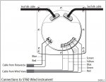
But problem seems to be input voltage. Supposed to be 8v but when connected to my Seatalk network there are 10.8v going up to the transducer and I’m guessing that’s what is messing with all the other test voltages which are out.

Any ideas?

I am contemplating getting some resistors and putting them in series with the red wire between head and vane to get volts down to 8 and retest. Anything wrong with that?

rest of system - depth, log, auto, remote pilot, plotter, Ais , radar, all work fine and am disinclined to mess with it.
 

V1701

Well-known member
Joined
1 Oct 2009
Messages
4,633
Location
South Coast UK
Visit site
I don't mean to be flippant but if you've done without it for years why bother? And if you do the chances are the plastic vane will get broken just after you fixed it...:oops:
 

Martin_J

Well-known member
Joined
19 Apr 2006
Messages
4,483
Location
Portsmouth, UK
Visit site
The 8v across the supply wires come from the electronics within the head unit rather than direct from the Seatalk bus. It's worth a try. It could just be the voltage regulator in the head unit that would normally drop the voltage to a constant 8v that's gone awry.
If not then new head unit.
 

Donheist

Active member
Joined
10 Mar 2012
Messages
256
Location
Marina Sant Elmo Alghero Sardinia
Visit site
Will experiment with battery voltage. It is the same with two separate wind indicators.

why bother? It’s more of an intellectual challenge than a necessity - and it helps teach my kids wind awareness when they can see the yellow arrow on the plotter. its The last job on my list and I’m having a brief moment of completer-finisher. I’m sure it will pass….
 

JumbleDuck

Well-known member
Joined
8 Aug 2013
Messages
24,165
Location
SW Scotland
Visit site
I am contemplating getting some resistors and putting them in series with the red wire between head and vane to get volts down to 8 and retest. Anything wrong with that?
Resistors only really work for reducing the voltage to something which looks like a resistance, and systems with active components tend not to. I think it would be better to use a proper convertor: something like LM317 DC Linear Converter Buck Step Down Low Ripple Module Power Supply CF UK | eBay, which does 1.2-37V out from 4.2 - 40V in and therefore ought to be able to give you 8V from 12V. Mind you, even better would be finding out where the 8V is supposed to be coming from and making sure it does ...
 

Donheist

Active member
Joined
10 Mar 2012
Messages
256
Location
Marina Sant Elmo Alghero Sardinia
Visit site
Resistors only really work for reducing the voltage to something which looks like a resistance, and systems with active components tend not to. I think it would be better to use a proper convertor: something like LM317 DC Linear Converter Buck Step Down Low Ripple Module Power Supply CF UK | eBay, which does 1.2-37V out from 4.2 - 40V in and therefore ought to be able to give you 8V from 12V. Mind you, even better would be finding out where the 8V is supposed to be coming from and making sure it does ...

good call. Ordered one of those. I agree best to fix properly but at least if I can get 8v to my transducer I can satisfy myself that the problem is at the bottom not the top. Then I can ebay my spare kit and maybe buy a new head.
 

Mistroma

Well-known member
Joined
22 Feb 2009
Messages
4,936
Location
Greece briefly then Scotland for rest of summer
www.mistroma.com
The 8v across the supply wires come from the electronics within the head unit rather than direct from the Seatalk bus. It's worth a try. It could just be the voltage regulator in the head unit that would normally drop the voltage to a constant 8v that's gone awry.
If not then new head unit.
I assume that you aren't referring to the masthead unit when you say head unit. I think the power supply comes from the ST60 display head and imagine that's what you mean (in case OP wasn't certain).

I was lucky when mine became dodgy several years ago. I did a lot of testing and finally traced it to poor connection at the masthead. I cleaned verdigris from the connector and applied some Contralube 770. It has been perfect ever since. Unfortunately, OPs problem seems to be the the supply.

I do remember that the spec. said 8V +-0.25V on the red and black wires going up to the masthead. I certainly didn't see 10.8V.

I should still have a copy of Raymarine's document describing the test procedure.
 
Last edited:

Martin_J

Well-known member
Joined
19 Apr 2006
Messages
4,483
Location
Portsmouth, UK
Visit site
Thanks and yes, I did mean the voltage is supplied from the display (head) and not from the MHU (masthead unit)..
Screenshot_20210807-185445_Drive.jpg
I've not got the circuit diagram to hand but I would expect a voltage regulation circuit of some sort to supply the consistent 8v.
 

Mistroma

Well-known member
Joined
22 Feb 2009
Messages
4,936
Location
Greece briefly then Scotland for rest of summer
www.mistroma.com
The tests I think are here..

Raymarine wind transducer test
I had a quick look through my files and found that page plus another document with similar information but possibly better layout. I have the service manual and it shows the 8V and Gnd connectors on the ST60 display plus test point on PCB to check for 8V. I can give these to the OP if it helps and will have a quick look over the circuit diagram to see if there's an obvious method of adjusting the output on the PCB.

EDIT:
I've had a very quick look at the circuit diagram and it looks as if the 8V supply comes from an L78L08. It looks pretty standalone on the board with 12V in and 8V out with no adjustment.

If OP has measured the voltage near the base of the mast then I think he should unplug at the display head and check there. If the vane connector at the display is 8V at that point there might be a short somewhere on the wire up to the masthead.

I'm assuming that OP doesn't have the old Rotavecta type masthead unit when mentioning the circuit data above. However, I think it is still meant to be 8V supply for that unit.
 
Last edited:

Donheist

Active member
Joined
10 Mar 2012
Messages
256
Location
Marina Sant Elmo Alghero Sardinia
Visit site
good call. Ordered one of those. I agree best to fix properly but at least if I can get 8v to my transducer I can satisfy myself that the problem is at the bottom not the top. Then I can ebay my spare kit and maybe buy a new head.
I had a quick look through my files and found that page plus another document with similar information but possibly better layout. I have the service manual and it shows the 8V and Gnd connectors on the ST60 display plus test point on PCB to check for 8V. I can give these to the OP if it helps and will have a quick look over the circuit diagram to see if there's an obvious method of adjusting the output on the PCB.

EDIT:
I've had a very quick look at the circuit diagram and it looks as if the 8V supply comes from an L78L08. It looks pretty standalone on the board with 12V in and 8V out with no adjustment.

If OP has measured the voltage near the base of the mast then I think he should unplug at the display head and check there. If the vane connector at the display is 8V at that point there might be a short somewhere on the wire up to the masthead.

I'm assuming that OP doesn't have the old Rotavecta type masthead unit when mentioning the circuit data above. However, I think it is still meant to be 8V supply for that unit.


I do mean the display head not masthead. I have tested volts at the red and black vane connections at the display and got 10.8v. The other voltages are out per that test sheet. I have both types of transducer.
Interesting re l78l08. I could try and replace that or just fix downstream with an external voltage regulator then between red terminal and red wire to transducer? Thanks fir all the advice!
 

Mistroma

Well-known member
Joined
22 Feb 2009
Messages
4,936
Location
Greece briefly then Scotland for rest of summer
www.mistroma.com
I do mean the display head not masthead. I have tested volts at the red and black vane connections at the display and got 10.8v. The other voltages are out per that test sheet. I have both types of transducer.
Interesting re l78l08. I could try and replace that or just fix downstream with an external voltage regulator then between red terminal and red wire to transducer? Thanks fir all the advice!
Let me know if the service manuals would be of any use. I'm assuming it's the newer masthead unit and analogue ST60 display. I might have documents for older masthead unit and even older Rotavecta.

I know that some chips allow you to select different voltages by shorting various pins or connecting to earth. I don't think that's the case with the chip fitted. It might be worth looking at the board in case it is a different chip and some solder is dodgy.

The connections should be something like this:
  • Pin1 VOUT (8V)
  • Pins 2,3,6 & 7 connected to Gnd via TP13
  • Pin 4 NC marked TP11
  • Pin 5 NC marked TP13
  • Pin 8 VIN (12V)
Perhaps a different chip might use 2,3,6 or 7 to determine output voltage. A long shot though as I'm pretty certain that the standard L78L08 8 pin chip just has 2,3,6 and 7 all connected internally and also to Gnd (i.e. Just 8V output, not adjustable).
 
Last edited:

Donheist

Active member
Joined
10 Mar 2012
Messages
256
Location
Marina Sant Elmo Alghero Sardinia
Visit site
Update! Soldering a mew regulator into the head display is beyond my dexterity so I bought one of the ebay regulators. Got 8v going to the masthead. Volts to yellow blue and green still not right. Yellow is getting 9v.

I could get spare transducer and try it: then climb up (need to replace anchor light bulb anyway :( ) but I’m starting to think it’s time to replace with wireless.

many ideas what I need? St60 seatalk everywhere else.
 
Top