Where to start with a high swr reading

chris-s

Well-Known Member
Joined
24 Apr 2019
Messages
816
Visit site
After being persuaded by you lot to use a splitter rather than a separate ais antenna, I returned the antenna and orders a splitter. I eagerly fitted it all last evening. However, it was showing an error light when transmitting on high power. I also took with me a spare banten antenna/cable with the idea of transmitting ais on that and checking I could receive it.

When using this antenna instead of the masthead, I do not get the warning light.

After a bit of swapping bits around it looked like using the masthead antenna was not working very well. We rarely use the vhf tbh, so might not have been aware of an issue.

This was a new antenna last year with all new cabling and connectors in one single unbroken length all the way to the radio. Being so new I was surprised at this.

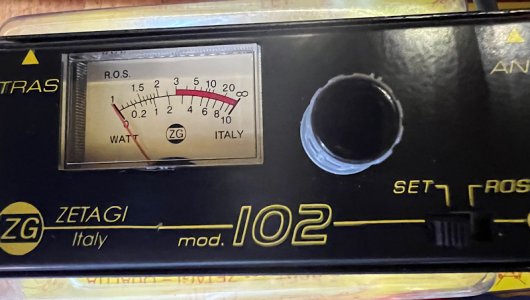
This evening I took down my zetagi 102 swr meter. I know how to use it, and when testing between the radio and the masthead (no splitter) I couldn’t get it ‘set’ to the max division, only as far as ‘20’ on the ros scale, then when checking it the needle went right up to 15. Clearly something wrong.

Testing with the spare banten antenna/cable gave readings that I would expect to see as more sensible.

A quick look up the mast and the antenna is still there (you never know).

Other than pulling the connectors apart, or swapping it all out I’m not sure where to start. I know it doesn’t mean much,but I stuck a multimeter on the ends to check for open/short circuit and both antennas read just under an ohm.

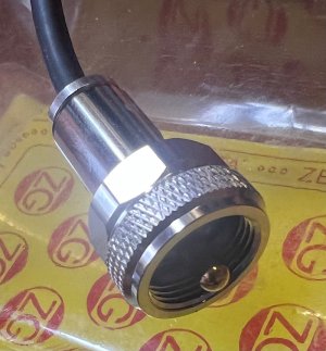
The connectors are m&p weatherproof ones so should be good quality. The cable is labelled “M-17/20-RG058 MIL-C-17G 50ohm”, again, this is supposed to be a good quality cable. I don’t recall what the antenna is, will need to look back thru my emails for a receipt.

Right now it looks like rather than having a short stumpy ais antenna on the pushpit, I’m going to end up with a flipping great banten job.

Thoughts on finding the fault?
 

Attachments

  • IMG_2025-07-01-182611.jpeg
    IMG_2025-07-01-182611.jpeg
    117.5 KB · Views: 21
  • IMG_2025-07-01-184221.jpeg
    IMG_2025-07-01-184221.jpeg
    191.6 KB · Views: 19
I had to replace our antenna a couple of years ago but I didn't bother with the cable at the time. The new antenna had a slightly different connector (mating surface on old was flat vs ridged on new). Our AIS signal was poor, although the VHF was fine. I replaced the cable earlier this year with the one that was supplied with the new antenna and the AIS signal is massively improved. I'm not sure if it was the connector actually mating with a better connection or if it was the matched cable/antenna combo that was the solution though.
 
The idea with an SWR meter is you select forward power, set the dial so the meter reads full scale then switch to reverse and read the SWR from the scale. If you can't get the meter to full scale it is likely because the SWR is really poor and the tx has reduced power to protect itself, so set it as high as you can and then try and read the SWR. It won't be accurate but will give you an idea.

do that and tell us how really poor it is.
 
Oh, it’s really really really poor 😕

As am I, since it turns out the antenna i had wasn’t optimal for ais, so I’ve ordered a new one any how and you never know it might be a faulty antenna despite it being little over a year old (wishful thinking).
 
I have recently had a similar experience.
The two Metz antennae gave different results, one acceptable one not.
Examination at the masthead revealed one disconnected inner and both connectors in far from good shape.
They are a right-angled variety to help with the lead. Strangely, although they seem to be well made, both have a steel washer around the outer and both washers were rusty. This was despite the self amalgamating tape wrapping.
The replacement connectors still have the steel washer which I will attempt to replace with stainless.
 
Thoughts on finding the fault?

Just checking, you're testing VHF - SWR Meter - Antenna at the VHF end of the cable run and getting a poor SWR (enough to get an error signal)

The good news is that the error signal probably means the device is cutting the power rather than heating the power amplifier.

Some ideas to try:
1) the ideal measure of VSWR for an antenna is at the antenna base - can you send someone up the mast to test a) the power coming out of the coax at that point and b) the VSWR of the antenna alone?
2) are you sure the antenna is complete? Can you get a nanoVNA and run a frequency vs VSWR sweep to see if it's tuned at any nearby frequency? If a bit of the radiator is missing it will change the tuning frequency.
3) If it's not the antenna, something else is causing a reflection, dodgy connector, broken cable etc. Is there a connection at the base of the mast? If there is can you use a dummy load to see if the problem is before or after the mast connector?
 
As ProDave has mentioned, although I haven't used that particular meter, I would have expected you to be able to calibrate the needle to the top of the range (infinity) when in the SET mode...

The lower scale is the SWR, ROS (although you could think of it as Reflected Outgoing Signal).

If this failure to fully SET is due to the radio considerably reducing power output, this could also indicate a problem with the feed line or the antenna.

You mention 1 ohm when measured between centre and outer braid with a multimeter.. This might also be important..

I can't find the detail on the Shakespeare website but a few other websites do indicate this ..

20250701_214029.jpg
I know that some antennas indicate 10K ohm and some are short circuit, but from the above, I would expect infinite resistance when measured between centre and outer braid.

Could you perhaps have just a single strand of the outer braid touching the centre core (within one of the two plugs) that gives rise to this 'just under an ohm' measurement.
 
Aplogies... I had the scales wrong in my mind.

The top scale is the SWR.. and lower is the power..

So I guess it's the lower scale where you need to calibrate to the top, if there is a calibrate knob.

Do you have the instructions for this meter that say what the SET should do?

I think it was the original post mentioning a set of 20 on the ROS scale that caught me out..
 
I know that some antennas indicate 10K ohm and some are short circuit, but from the above, I would expect infinite resistance when measured between centre and outer braid.

Could you perhaps have just a single strand of the outer braid touching the centre core (within one of the two plugs) that gives rise to this 'just under an ohm' measurement.
DC resistance is wholly dependant on the antenna design - it can be any figure.

What's important that it's AC impedance is close to 50 at the operating frequency.
 
Agreed... However due to the varying construction of marine VHF antennas some antennas show a short at DC (0 ohms), some show open circuit, (v high ohms) some show a resistance (some ohms).

Some manufacturers do state what the DC ground continuity test should read..


E.g. V-Tronix about 10K ohm..

Screenshot_20250702-172437_Samsung Internet.jpg

And Shakespeare 5215, open cct..

20250701_214029.jpg

And in the case of the original [Edit: second] post, it appeared to be a 5215 series antenna, so at DC it should show open circuit, not the slightly under 1 ohm as measured by the OP.
 
Thanks for all the replies some useful bits there.

@Martin_J yes, I noticed that information about the dc open circuit last evening too.

@st599 yes, the swr meter is at the bottom end of the cable. When ‘setting’ the meter I was able to adjust it to get the needle to just above ‘20’ on the scale in the photo and then when measuring it deflected to around ‘15’ on the scale, way too high!

I’ve ordered a replacement antenna anyhow as that one wasn’t tuned ideally to suit ais and some new connectors.

The m&p connectors can be fiddly to assemble because but that should make it quite unlucky to get a stray wire in the wrong place but of course not impossible. This also makes them a bit fiddly to dis-assemble to see if you can visibly see a problem.

Looks like a trip, or two, up the mast are imminent <sigh>.
 
Actually, another thought, replacing the connector at the top of the mast is going to be enough of a pita without the fiddly-ness of assembling one of these m&p ones, soldering would be bad enough!

Perhaps I should look for a ‘crimp’ style pl259 kit for the top…if it does end up needing to be replaced.
 
If there really are just two plugs in the system, I'd open the one you can reach first.. and check for a loose strand..

Then I guess it could be a trip up the mast to unplug.. and with both ends of the co-ax unplugged, you should see DC open circuit between centre and outer braid on the co-ax.

If you've got the multimeter at the top at that point, you could check across the antenna connections... Do confirm if you can exactly which Shakespeare antenna it is because it would be nice to confirm if it really should be open circuit and not that 1 ohm as measured previously.

This should hopefully then indicate which way the fault lies...

The antenna you found is the ais version of the one i currently have, that also makes the same statement regarding dc open-circuit.

The ais variant, as you pictured, is what I have now ordered.

My plan of attack sounds pretty much like you suggested.

Thanks again.
 
Right, problem solved - pulled apart the connector on the bottom end and it was clear to see that when soldering on the tip it melted the centre core insulation. An embarrassingly poor soldering job. I recall when I did it that I felt it wasn’t as good a job as the other end which I did in the workshop.

Cut the end off, multimeter read open circuit. Fitted a new connector, not the same type but a similar style except that the core extends right thru to the tip of the centre pin making it much easier to assemble and solder.

SWR meter gave much better readings. I’ve got an ais version of the antenna coming so will give the top end a good check when I’m up there.

Please don’t judge my soldering, I usually do a much better job but had to do this join in situ on a bouncy boat with a rubbishy gas soldering iron and no helping hands, that’s my excuse anyhow. I’ve now got a Milwaukee cordless one which is fantastic. Anyhow if you look closely you can see there is no centre core insulator. The fitting instructions require only 1mm of insulator protruding from the insulating washer, so very tight.

IMG_2025-07-03-213328.jpeg
 
The 1ohm DC resistance measured by the multimeter did give the good clue then...

And once the plug had been chopped off, the new reading also gave a good clue as to your progress...

It would be nice if all manufacturers could give an indication of the expected DC resistance between centre core and shield.

Glad it's fixed and that the SWR reading is better.

Out of interest... When the meter switch is set to SET... do you dial the needle to max or to the actual power expected from the radio... ?

(Only asking because my meters have always had 'calibrate' and 'power' switch settings but not a SET. Your meter also has power indicated on the display but no visible switch setting for 'power' ).
The ‘set’ I guess is the same as your ‘calibrate’ and, as per the instructions, I adjust it so the needle is on the maximum/ full range division whilst transmitting on ‘low power’. I repeat the test on several different channels, avoiding #16! I’ve never taken much noticed of the actual values on the scale, the amount of deflection is usually enough to indicate how bad things are.
 
Thank you..

It looks like the WATTS scale isn't used then..

On the meter I currently use, the calibrate is done by setting to the CAL mark on the display. You can also switch and look at forward power (so you know how much power the radio is putting out), then you can look at reverse/reflected power and you can then switch and look at SWR..

OneDrive Video showing the extra switch settings.. (Apologies for my quiet voice in the video).

Microsoft OneDrive - Diamond SX-200 in use

Screenshot_20250704-084916_Samsung Internet.jpg

Looks like it also copes at various power ranges more easily as well.. Just a thought next time you're looking for a new toy!
 
Top