'Weird' p-bracket

slawosz

Active member
Joined
26 Sep 2018
Messages
623
Location
London
Visit site
Hi,
The dreaded set screws turned out to be no issue for my P-bracket, but, after comparing it with other brackets in the club, I noticed mine is weirdly built. It appears to have an internal rim that is blocking access to the cutlass bearing from the shaft side. It appears I cant remove the bearing without removing the shaft, and even then I probably need to use a hacksaw to remove the old bracket.
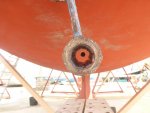
Have you seen something like this before? Photos and drawings below, full CAD drawing: Fusion

Prop side: I think there is little of the bearing tube here:

Shaft side - tube hidden.

Entire p-bracket crossection:

Crossection without bearing:

free image hosting
 

Pete735

Member
Joined
13 Nov 2004
Messages
402
Location
South Wales
Visit site
Yes, I found exactly the same thing on my P bracket last year, much to my consternation. I had to drop the rudder to remove the prop/propshaft and then use an electric saw to put 2 longitudinal cuts down the cutless bearing and through the internal collar. I borrowed a Milwaukee sabre saw and it made short work of the job. Straightforward enough to then replace the bearing (more a water lubricated bush). It has left me with two cuts in the collar but that's not an issue.

I toyed with the idea of cutting this internal collar section off which I could have done on mine as it was in a sort of nose on the P bracket. I only decided not to because I knew why my cutless bearing had failed, the nuts on the threaded section of one of the engine supports had come loose so the engine was sitting at an angle on one corner, so I reckoned if I changed the cutless bearing and locked the adjustable legs/nuts properly there was no reason the setup would not last for many a year.

As to why some boats have this type of P bracket, I do not know and can see no real benefit plus I did talk to a supplier/repairer of stern gear and he did not know either.
 

ianat182

Well-known member
Joined
10 Jul 2008
Messages
2,689
Location
,home Portchester
Visit site
I have heard that some of these Cutless bearings are supplied as two separate halves, perhaps why they have a lip on each end.
This must give owners a problem removing them where using a threaded studding and a plate or socket to withdraw them is generally straightforward, though I guess the hacksaw method does it -though hard work to withdraw needing the shaft out of its coupling and leading to possible alignment errors.
 

johnalison

Well-known member
Joined
14 Feb 2007
Messages
41,974
Location
Essex
Visit site
The P bracket isn't vertical, it hangs at an angle to starboard so the shaft isn't directly inline with the skeg and can be removed with the prop off.
View attachment 132830
At least some Sadler 32s had an offset shaft, supposedly to counter prop walk. A friend had one and on their first cruise the shaft became disconnected from the engine and it was only by a fluke that the 2-bladed prop met the rudder on its attempted bid for escape.
 

ianat182

Well-known member
Joined
10 Jul 2008
Messages
2,689
Location
,home Portchester
Visit site
Looking at your drawings of the P bracket is it possible that there is an error? It shows an internal lip on the p bracket itself which would prevent removal by any means. My guess is that there is not a 'lip' but has to be driven out from engine side to prop side. I guess when inserted it was with a sealant so a kind of penetrating inserted through the grub screw hole might help free the bearing, maybe a heat gun to soften the sealant. Replacing would seem to be easier beihg fitted from the prop end.
 

Graham376

Well-known member
Joined
15 Apr 2018
Messages
7,944
Location
Boat on Mooring off Faro, Home near Abergele
Visit site
Looking at your drawings of the P bracket is it possible that there is an error? It shows an internal lip on the p bracket itself which would prevent removal by any means. My guess is that there is not a 'lip' but has to be driven out from engine side to prop side. I guess when inserted it was with a sealant so a kind of penetrating inserted through the grub screw hole might help free the bearing, maybe a heat gun to soften the sealant. Replacing would seem to be easier beihg fitted from the prop end.

It's not an error in drawing although possibly a design error, There's a lip on ours as well as other models of Moody boats.
 

burgundyben

Well-known member
Joined
28 Nov 2002
Messages
7,484
Location
Niton Radio
Visit site
Putting a cutlass bearing in a p bracket like that where one end has reduced diamter thys making removal much more difficult seams really ill thought out.

I cant think why it would be done like that.

I reckon if that was mine I'd be whipping the p bracket off the boat and modifying it.
 

slawosz

Active member
Joined
26 Sep 2018
Messages
623
Location
London
Visit site
I am thinking about using hole cutter to remove the lip. I will make 3d printed guide for the cutter drill so it will be straight. Of course I will talk to surveyor first.
 

HissyFit

Active member
Joined
13 Jul 2020
Messages
682
Visit site
Looking at your drawings of the P bracket is it possible that there is an error?
It's not an error in drawing although possibly a design error, There's a lip on ours as well as other models of Moody boats.
I don't see an error, in either drawing or design. The lip may have been considered to have been necessary to prevent the cutlass bearing from working backwards out of the P bracket. A correctly designed puller would be a good thing to have to pull the cutlass bearing out towards the prop end.

Actually, I did see a drawing error: It is not traditional drawing practice to cross-section shafts or keyways. Also the rotational axis of the shaft is not indicated with a line of short-long dashes. (Ignore the last: it doesn't matter a fig if the meaning is clear.)
 

slawosz

Active member
Joined
26 Sep 2018
Messages
623
Location
London
Visit site
The lip may have been considered to have been necessary to prevent the cutlass bearing from working backwards out of the P bracket.

Right, however in my case anode would prevent from sliping out .

A correctly designed puller would be a good thing to have to pull the cutlass bearing out towards the prop end.

Do you have ideas how such puller looks like?

Actually, I did see a drawing error: It is not traditional drawing practice to cross-section shafts or keyways. Also the rotational axis of the shaft is not indicated with a line of short-long dashes. (Ignore the last: it doesn't matter a fig if the meaning is clear.)

Oh well, its for clarity, if you have some good guides online how to make such drawing properly, it would be appriciated :)
 

ianat182

Well-known member
Joined
10 Jul 2008
Messages
2,689
Location
,home Portchester
Visit site
There would appear to perhaps be some indication of marks around the outer lip perhaps a punch or hammer mark. It seems that the only kind of extractor tool might be in the form of an adjustable reaming tool, but an internal clamp perhaps in order to withdraw the internal material for it to work on the sleeve outer. I would guess that the bearing was bench pressed in the P bracket before assembly into the hull.
 

Pete735

Member
Joined
13 Nov 2004
Messages
402
Location
South Wales
Visit site
Just so you don't waste any time on it I had a split collar made to fit just inside the end stop. A couple of jubilee clips to hold these collars to the propshaft gearbox side) and then a conventional cutless bearing puller to pull the cutless bearing out. It doesn't work because the split collars are loading up the rubber bush of the cutless bearing and actually squashing it tighter to the propshaft. I hope my explanation makes sense, it's tricky to explain in text but option 2 was rudder and prop removal and a few minutes with the sabre saw.

Almost certainly the bearing was fitted into the P bracket with a bench press as in a factory that's the logical way to do it, but it slides in easily enough with a length of studding and a couple of large washers - just like any bearing, as it's only a mild interference fit being a thin brass (by the look of it) outer shell with a rubber insert. Nothing high tech about a cutless bearing other than perhaps the rubber compound used.
 
Top