Volvo Penta D2 MDI failure - what are the typical symptoms?

Samwise2111

New member
Joined
28 Apr 2024
Messages
15
Visit site
As for symptoms.. There were none... Just instantaneous failure.
If there is nothing burnt on the PCB, but it still does not work and shows no reaction to the push of any button, we would be interested in getting our hands on one. Or any that have these symptoms, so that we can continue the research. The box might be repaired in the process (no promises, as it depends on the cause of the failure).

My MDI had two issues:
1. An MLCC was broken and had become slightly conductive. As a result, a button was permanently recognised as pressed, which sent the LPC into the bootloader. Then it is still up and running, but it will not react to any buttons nor switch power to the panel etc.
2. The LPC should go into power-down mode when not in use. It did not. It got stuck in the process. This is a strange error. It may indicate a defect in the LPC. But after desoldering, the LPC worked just fine, as does a new one soldered onto the PCB.
So we cannot investigate the cause - because my MDI is now repaired..
 

woodstock37s

New member
Joined
2 Jun 2020
Messages
2
Visit site
Hi all, we have another MDI (23195776) with a failure.
no buttons of the control panel seem to cause any reaction, display are off.
Had to Jump-start the motor and luckily found a spare MDI unit on our boat.
The engine D2-40 from 2017.
today I opend the housing. from my perspective no visible damages to the PCB.

Any Ideas, what I could test to narrow down the possible failures? which MLCC was broken?
And also: where did you send your MDI to for a repair?
 

Beneteau381

Well-known member
Joined
19 Nov 2019
Messages
2,026
Visit site
My D1 30 of 2017 vintage and relatively light use has had three MDI failures... 4th box fine so far... Bypass switches installed for glowplugs and starter motor installed as backup. Online searches indicate possible cause being a back EMF from the fuel shut off solved by a simple diode across the solenoid....earlier engines had relays in the control box rather than the solid state version in current engines and did not suffer this problem....
I was involved in a case about 3 years ago and helped a Brazilian guy lean on VP. They eventually sent two Swedish techies to Portugal with a scope and pinpointed what myself and the wife had spotted with a multimeter, a slight surge, barely noticeable but the scope showed it. The back EMF from a mechanical relay was indeed frying the boxes, he had had 4 fitted. As you say a diode was fitted across the offending relay and the problem was solved. A former editor of PBO was chatting to me and he expressed surprise that the relays used weren’t fitted with flyback diodes as standard.
 

Samwise2111

New member
Joined
28 Apr 2024
Messages
15
Visit site
Hi @woodstock37s,
I'm on the boat right now, sailing. So I am away from my lab and do not have access to all of the information.
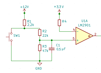
The circuit detecting the button press looks like this for each button:
Input_button.PNG
C1 is the culprit. If you look at the positive inputs of the LM2901 you should find a direct connection to an MLCC for each. Normally the voltage on the positive input should be larger than on the negative input. It is only pulled down to below the voltage on the negative input, when the button is pressed. If C1 is bad (i.e. conductive) the voltage on the positive input will always be lower than on the negative input, simulating a pressed button.

So what you can do is:
1. Follow the traces on the PCB and identify the MLCC for each button. Measure the voltage on the input channels of the LM2901. That's a bit delicate. There is not much space between the pins. You'll need the right tools in order not to short-circuit anything. If you feel this is not for you then:
2. Separate the PCB from engine and panel and power it up with 12V e.g. from a battery, ideally from a lab power supply. Measure the current. The circuit will be in different states depending on whether a button press was (erroneously) detected.
3. Solder wires to the RxD0 and TxD0 and "listen" to the communication with a 3.6V UART->USB adaptor. The microcontroller may be in bootloader or in debug mode, depending on which button was recognised as pressed.

I do not think you can just "send" the MDI box anywhere for repairs. I did some analysis myself and then worked together with a friend, who routinely examines automotive control units. I can give you his address. He'll certainly be interested in examining your unit as well. Or you'll have to wait until I will be back home, later in July. In both cases, of course, there are no guarantees...
 
Last edited:

Beneteau381

Well-known member
Joined
19 Nov 2019
Messages
2,026
Visit site
Hi all, we have another MDI (23195776) with a failure.
no buttons of the control panel seem to cause any reaction, display are off.
Had to Jump-start the motor and luckily found a spare MDI unit on our boat.
The engine D2-40 from 2017.
today I opend the housing. from my perspective no visible damages to the PCB.

Any Ideas, what I could test to narrow down the possible failures? which MLCC was broken?
And also: where did you send your MDI to for a repair?
I doubt any one would repair such minority parts or know how to. BUT if you can find a computer motherboard repairer they might have a go. IIRC it was the MOSFETS that got fried. Basically electronic switches that use a signal to a “gate” to open and close circuits. The manager for VP for Spain and Portugal pitched up and told my Brazilian mate with the problem that the box controlled the fuel system to cope with the new regs to deal with new EU legislation on exhaust emissions. A load of cobblers! The base engines were Perkins 400 series, mechanically injected engines with no electronic fuel control. The boxes controlled electronically the glow, start and stop with mosfets switching the functions as I understand it. It’s other function was as I understand it to convert engine data so that it could be read on the new multi function displays. My mate in despair actually got Beta Marine with my help to build him a mechanical wiring system with a Beta panel as a get him home to Brazil.
VP finally fixed it but he spent months in my marina in his brand new alloy boat trying to get it fixed. They gave him the new wiring harness off one of the old mechanical electric systems as well as a few MDI boxes.

PS it was the large relay fitted by the alloy boat manufacturer to isolate the engine from the hull that was the culprit doing the back feeding
 
Last edited:

Samwise2111

New member
Joined
28 Apr 2024
Messages
15
Visit site
IIRC it was the MOSFETS that got fried.
Woodsock37s' version 23195776 of the MDI box uses Infineon IPB011N04LG MOSFETS in back-to-back configuration to switch glow plugs and starter motor.
They are good for 180A and 40V. If you fry them I bet you will not report "no visible damages to the PCB". You will smell and see the damage.

@woodstock37s: It would be interesting to know if there was a cause, like weak battery connection, high heat, just anything where you would say "this happened and then it was dead".
 

woodstock37s

New member
Joined
2 Jun 2020
Messages
2
Visit site
Thank you for all the ideas!
I cannot find a specific event, that could cause the (unvisible) damage.
The boat was out of the water for about a year. Lot´s of refit work was done, including a change to new LiFePo4 batteries (Service) and new charging/B2B, Solar Hardware.
After bringing it back into the water, the failure happened. So, could be, that higher voltage in the charging cycle caused a failure.

Will check the Unit by re-installing it, again. and after that re-check the PCBs.
 

Beneteau381

Well-known member
Joined
19 Nov 2019
Messages
2,026
Visit site
Woodsock37s' version 23195776 of the MDI box uses Infineon IPB011N04LG MOSFETS in back-to-back configuration to switch glow plugs and starter motor.
They are good for 180A and 40V. If you fry them I bet you will not report "no visible damages to the PCB". You will smell and see the damage.

@woodstock37s: It would be interesting to know if there was a cause, like weak battery connection, high heat, just anything where you would say "this happened and then it was dead".
I was given the word that it was MOSFETS, however the fact that VP manager told my mate that the MDI controlled the emissions and fuel system says it all.
The bottom line however is that it was voltage surges caused by coils in relays/solenoids switching on? and off and that a diode across the relay ( flyback diodes? ) cured it?
That capacitor you pointed out? Would that be damaged by voltage from coils switching?
 

Beneteau381

Well-known member
Joined
19 Nov 2019
Messages
2,026
Visit site
Thank you for all the ideas!
I cannot find a specific event, that could cause the (unvisible) damage.
The boat was out of the water for about a year. Lot´s of refit work was done, including a change to new LiFePo4 batteries (Service) and new charging/B2B, Solar Hardware.
After bringing it back into the water, the failure happened. So, could be, that higher voltage in the charging cycle caused a failure.

Will check the Unit by re-installing it, again. and after that re-check the PCBs.
You will need someone with circuit board repair skills to check and fix it
 

Samwise2111

New member
Joined
28 Apr 2024
Messages
15
Visit site
Back in port now and I finally have some time...
I was given the word that it was MOSFETS
That may very well have been the problem in your friend's case. But it takes something to toast these MOSFets and I doubt that you would diagnose "no visible damages to the PCB" afterwards, as woodstock37s did. So his case may be entirely different.
the fact that VP manager told my mate that the MDI controlled the emissions and fuel system says it all.
Yeah, well, he couldn't have simply said that the MDI box doesn't do you any good at all, but only has the value for VP to be able to offer a variety of their CAN bus linked panels...;)
That capacitor you pointed out? Would that be damaged by voltage from coils switching?
No. If a voltage spike were to reach this point, it would have already destroyed so many other parts along the way...
This capacitor dies of old age, accelerated by heat and vibrations.
I have now measured it:
At an air temperature of 24°C (in the morning) and a water temperature of 26°C, the point on my engine where the MDI box is fitted quickly reaches a stable 85°C.
VP has eliminated many of the original weaknesses of the MDI box in the latest version, but there is one thing they can't do anything about:
Their poor choice of microcontroller. They chose one that became NRND shortly after the MDI box was developed and of which there are only "industrial grade" versions, no "automotive grade". "Industrial grade" = max. 85°C ambient temperature. AEC-Q100 defines automotive grade 0 as -40 to 150°C, grade 1 as -40 to 125°C and grade 2 as -40 to 105°C. There is a grade 3 that can be used for window lifter control units, but these are typically not screwed onto the engine... ;)

So if the motor is in thermal equilibrium with the 26°C cooling water at 85°C and you consider that the circuit itself consumes electricity and therefore generates heat, then it can be assumed that the microcontroller will be operated outside its specification for longer periods of time.
It will not die instantly, but its function is not guaranteed. In my case, while working through the program, it came to a point that was supposed to send it to sleep (or rather power down. Quartz oscillator off etc. But it didn't power off, it just got stuck. This was the case even after the capacitor issue was resolved.
It would be interesting to see if this is a common problem.
 

Samwise2111

New member
Joined
28 Apr 2024
Messages
15
Visit site
@woodstock37s
As I posted above, we would be interested in investigating this further.
So if you would like to send us your MDI box, please send me a PM. The MDI box could be repaired in the process, but I can't promise it. The fault could be a completely different one. Then it will first have to be found...
 

Beneteau381

Well-known member
Joined
19 Nov 2019
Messages
2,026
Visit site
Back in port now and I finally have some time...

That may very well have been the problem in your friend's case. But it takes something to toast these MOSFets and I doubt that you would diagnose "no visible damages to the PCB" afterwards, as woodstock37s did. So his case may be entirely different.

Yeah, well, he couldn't have simply said that the MDI box doesn't do you any good at all, but only has the value for VP to be able to offer a variety of their CAN bus linked panels...;)

No. If a voltage spike were to reach this point, it would have already destroyed so many other parts along the way...
This capacitor dies of old age, accelerated by heat and vibrations.
I have now measured it:
At an air temperature of 24°C (in the morning) and a water temperature of 26°C, the point on my engine where the MDI box is fitted quickly reaches a stable 85°C.
VP has eliminated many of the original weaknesses of the MDI box in the latest version, but there is one thing they can't do anything about:
Their poor choice of microcontroller. They chose one that became NRND shortly after the MDI box was developed and of which there are only "industrial grade" versions, no "automotive grade". "Industrial grade" = max. 85°C ambient temperature. AEC-Q100 defines automotive grade 0 as -40 to 150°C, grade 1 as -40 to 125°C and grade 2 as -40 to 105°C. There is a grade 3 that can be used for window lifter control units, but these are typically not screwed onto the engine... ;)

So if the motor is in thermal equilibrium with the 26°C cooling water at 85°C and you consider that the circuit itself consumes electricity and therefore generates heat, then it can be assumed that the microcontroller will be operated outside its specification for longer periods of time.
It will not die instantly, but its function is not guaranteed. In my case, while working through the program, it came to a point that was supposed to send it to sleep (or rather power down. Quartz oscillator off etc. But it didn't power off, it just got stuck. This was the case even after the capacitor issue was resolved.
It would be interesting to see if this is a common problem.
OK
The issue that I was involved with was definitely caused by voltage spikes from coils in solenoids/relays. Basically fitting a diode cured it. My former editor was surprised that the relays associated with the box werent fitted with “flyback” diodes.
The collapsing voltage in the coils were causing spikes, much as a car ignition coil works. These spikes were damaging the box. What damage was being caused was articulated as being MOSFETS. Whatever your investigation comes up with? Well that is for you to find out. It is telling that after the Swedish techies went back to Sweden that the internet chat disappeared quite quickly.
The issue seems to have been fixed by the latest iteration of the boxes.
 

simon_ballantine

New member
Joined
27 Jul 2024
Messages
4
Visit site
After reading that article I designed my own hard wired system as the author pointed out there many components that will fail at various times -it was generally a unit not fit for purpose.
When our lives depend on the engine in certain situations you have to be certain its going to work when you need it most.
Did you replace the whole system? I want to do the same and would be very grateful for some advice. Did you keep a circuit diagram you could share?
 

Beneteau381

Well-known member
Joined
19 Nov 2019
Messages
2,026
Visit site
Did you replace the whole system? I want to do the same and would be very grateful for some advice. Did you keep a circuit diagram you could share?
In the incident I was involved with, the owner was that cheesed off,that with my help, he got Beta marine to build him a mechanical wiring system. It cost about £700 iirc. The previous version of the VP system was mechanical BUT at VP prices was stupid! Eventually VP solved the problem and fitted diode to cure it, they also gave him a mechanical wiring system and several MDIs
 

Beneteau381

Well-known member
Joined
19 Nov 2019
Messages
2,026
Visit site
Thanks for that. If its OK with you then I will give you a call when I'm back home in September. I'm above the artic circle in Norway at the moment, with a failed MDI- fortunately I had rigged an emergency start button....
Basically you can buy a Betamarine engine control panel and wire that in instead of the MDI.
 

Samwise2111

New member
Joined
28 Apr 2024
Messages
15
Visit site
Did you replace the whole system? I want to do the same and would be very grateful for some advice. Did you keep a circuit diagram you could share?
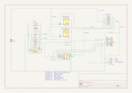
The attached diagram I used for initial planning.
There are many ways to replace the VP MDI-box and panel. You can buy (almost) any panel designed for mechanically controlled diesel engines.
Or google "Volvo Penta Doomsday box".

I bought an ignition lock (for farm machinery, like Deere tractors), two relays, fuses, cables, a cheap KUS rev counter, a power resistor (to precharge the alternator), and I CAD-designed a panel that would fit exactly where the VP panel was (but nicer ;-) ) and had it professionally made.
All together came out at £250.
To plug into the engine's MDI connector I used a pigtail Deutsch connector from here:
DT04-08PA-CE02-PT - Full assembled 8 Way Receptacle Deutsch DT-Series with Reduced Dia. Seal (E-Seal), black
This way I did not have to make any changes to the engine wiring harness.
 

Attachments

  • Lobo-Wiring.png
    Lobo-Wiring.png
    124.5 KB · Views: 3
Top