chris-s
Well-Known Member
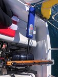
After all the replies a follow up…with the engine off, moving the tiller pilot closer and further away from the engine swings the tiller pilots compass by 30 degrees or more, with the tp in place and just turning the engine over it swings all over and when running it swings 20 to 40 degrees. It’s obviously the magnet used for the ignition. Engine off and under sail it performs fine.. What it needs is an optically triggered electronic ignition (possibly)
I might look at selling it and putting the funds towards the pcnautic unit.
I might look at selling it and putting the funds towards the pcnautic unit.