Switch panel setup ?

Refueler

Well-Known Member
Joined
13 Sep 2008
Messages
23,799
Location
Far away from hooray henrys
Visit site
I am replacing the original panel which has various items no longer functional or needed ... its a resonable sized panel and I am considering having two switch panels fitted to a new base plate ... one panel powered by domestic bank (2 x 80AH Lead Acids) and other panel powered by the starter battery (1 x 80AH Lead Acid)

Charging is governed by a relay that closes when engine starts .. and also by dual output Victron - so please - I am not replacing LA's with LiFePo4 ..
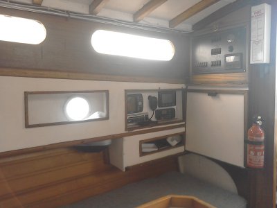
Old panel :

Visible panel size.jpg

The matter is the two panels I have are :

New panel x2.jpg

Idea to have two of them arranged with Ammeters as well ... one panel for each bank.

possible new.jpg

Below each switch a fuse covering that function

The question :

What items to connect to which panels switches .. there being 6 switches per panel ..

We have the normal :

Nav lights
Steaming Light
Anchor light
Tricolour
Nav Instruments
Bilge Pump over-ride
Music

mmmm anything else and which ones to which bank ? Or all to domestics and only connect starter batt to meters ? I'm not inclined to have starter via a swap-over switch to power the whole lot ... prefer to keep the single battery separate.
 
How about switching the onboard usb 5v out or voltmeters off to save current draw when they aren’t in use? I did that on a similar panel. My panel was bought from eBay and I didn’t realise how much of it lights up like a blue Christmas tree, or I would have chosen another with less lights.
 
Not sure of the benefits of ammeters and voltmeters when a battery monitor can give you the same information. Equally don't see the necessity for a switch panel for the start battery.

This is my house DC panel.
 

Attachments

  • IMG_20220426_144042.jpg
    IMG_20220426_144042.jpg
    720.8 KB · Views: 19
I arranged 2x6 way panels as day/night. Night panel has Nav lights, Steaming, Tri, Compass, working, cockpit lights. Day panel has Auto helm, GPS, VHF, depth sounder, 12V sockets, cabin lights. A quick look at the panels when daytime sailing makes it easy to spot a circuit that's "ON" that should be "OFF"
 
I arranged 2x6 way panels as day/night. Night panel has Nav lights, Steaming, Tri, Compass, working, cockpit lights. Day panel has Auto helm, GPS, VHF, depth sounder, 12V sockets, cabin lights. A quick look at the panels when daytime sailing makes it easy to spot a circuit that's "ON" that should be "OFF"

mmm never thought of it that way ...

I'm open to ideas of how to use ..
 
Not sure of the benefits of ammeters and voltmeters when a battery monitor can give you the same information. Equally don't see the necessity for a switch panel for the start battery.

This is my house DC panel.

It was while the two panels were sitting on my desk .. the idea to separate items to battery bank based on what is used when such bank is used ...

Example - Steaming light would be starter battery bank when engine is used. Anchor light when all stopped and using domestic bank.

But as I sat and jotted down the items - I found that most would fall to the domestic bank ... with very little to starter bank.

As to Battery monitor ... the existing panel has a Voltmeter that shows the domestic panel as soon as the isolator switch is closed. Its there plain as anything .. Open the isolator switch and panel / meter is no longer powered.
Thoughts again when the panels were on the desk - why not know the state of each bank similarly ? The ammeter on original panel was broken .. but obviously someone in the past thought it was a good idea .. I tend to think that as well ... nice to glance at panel and know the amps at that moment .. I happen to like analogue needle meters and they are both +/- 10A meters.
 
As mentioned, you will have very little to the starter battery, my opinion would be to wire everything off the domestic and let the starter battery have it's one job.
You could replace one of the voltmenters with another USB or 12V outlet, I find I need a lot more USB outlets than I think these days (I am not a fan of disposable batteries).
It may not be desirable if you want individually redundant circuits, but it is possible to have nav light circuits for 'sail' (tricolour) and 'power' (nav+steaming), with a seperate one for anchor. This means one less switch with could be a spare for future expansion.

You might find there is a decent amount of wiring to remove from the ammeter circuit - we had meters of 6mm2 cable to remove on ours, it was very liberating.
 
We have the normal :

Nav lights
Steaming Light
Anchor light
Tricolour
Nav Instruments
Bilge Pump over-ride
Music

mmmm anything else
Do you have pressurised water? It’s nice to be able to turn that on/off if you have leak somewhere.

I’m guessing no fridge?
Domestic lighting?
And deck lighting or instrument back lights?
I have my “nav” instruments split into three - the actual instruments (wind, depth, ST1 network), the autopilot and plotter, AIS/wifi - admittedly just because that’s how it evolved but it’s useful that a fuse blowing fault on one won’t take out all three.
I assume you are wiring the VHF direct to the battery?
And do you have a diesel heater?
 
I'm a great fan of keeping the starter battery purely to start the battery. Sod's law is quite clear on the consequences if you don't. An emergency connection to allow starting from the domestic and running nav lights, etc from the engine battery, absolutely, but anything else strikes me as asking for trouble
 
As mentioned, you will have very little to the starter battery, my opinion would be to wire everything off the domestic and let the starter battery have it's one job.
You could replace one of the voltmenters with another USB or 12V outlet, I find I need a lot more USB outlets than I think these days (I am not a fan of disposable batteries).
It may not be desirable if you want individually redundant circuits, but it is possible to have nav light circuits for 'sail' (tricolour) and 'power' (nav+steaming), with a seperate one for anchor. This means one less switch with could be a spare for future expansion.

You might find there is a decent amount of wiring to remove from the ammeter circuit - we had meters of 6mm2 cable to remove on ours, it was very liberating.

I have a trailing USB on the chart table - has 4 outlets .... usually charging the LED extra cabin lights I have .. (magnetic jobs that sit under the shelving to give individual berth lighting... and one near the heads ..

I think I would still like to have the two voltmeters showing each bank ... they would both disconnect with isolator switches opened.

Its one of those sit the desk - units in front of you .... sheet of black acrylic ready to cut / fit as wanted

I did want to have a 'sailboat' on the panel with led's showing which lights on ... who knows - maybe I will !
The more common method with voltmeters is to fit one meter and a on-off-on switch, so the meter is normally off (using no power) and the switch selects with battery voltage is shown. Same with an ammeter. The modern method is to fit a decent battery monitor.
 
Do you have pressurised water? It’s nice to be able to turn that on/off if you have leak somewhere.

I’m guessing no fridge?
Domestic lighting?
And deck lighting or instrument back lights?
I have my “nav” instruments split into three - the actual instruments (wind, depth, ST1 network), the autopilot and plotter, AIS/wifi - admittedly just because that’s how it evolved but it’s useful that a fuse blowing fault on one won’t take out all three.
I assume you are wiring the VHF direct to the battery?
And do you have a diesel heater?
Diesel heaters must not have a switch, they should be wired directly to the battery. If you turn it off when it's running it doesn't go through it's cool down cycle, which can cause dame or even start a fire.
 
Diesel heaters must not have a switch, they should be wired directly to the battery. If you turn it off when it's running it doesn't go through it's cool down cycle, which can cause dame or even start a fire.
Whilst I agree with that - it doesn’t preclude a switch, it just means that the switch (and any isolator it goes through) should only be turned off after going through the proper shut down procedure. Not having a switch means you are leaving the parasitic load of the controller running in standby mode - which is about 4 Ah per week getting drained from your batteries. Enough to matter? Depends on the time between use, battery capacity etc, solar or shore power etc. If it’s really a fire hazard that means the fuse blowing can start a fire.
 
Whilst I agree with that - it doesn’t preclude a switch, it just means that the switch (and any isolator it goes through) should only be turned off after going through the proper shut down procedure.
To my mind, that's just opening the door to Mr Sod. Sooner or later, someone WILL forget about the shutdown procedure.

Would it be possible to have a self-latching relay fed from somewhere on the heater, so you could turn it off, but the power won't go off until it is shut down properly? - or a thermistor to keep the power on until it's safely cooled down?
 
Whilst I agree with that - it doesn’t preclude a switch, it just means that the switch (and any isolator it goes through) should only be turned off after going through the proper shut down procedure. Not having a switch means you are leaving the parasitic load of the controller running in standby mode - which is about 4 Ah per week getting drained from your batteries. Enough to matter? Depends on the time between use, battery capacity etc, solar or shore power etc. If it’s really a fire hazard that means the fuse blowing can start a fire.
If you're worried about the small drain when the boat isn't in use, connect the supply to the load terminal of the main battery isolator, perhaps with a warning sticker about allowing the heater to cool down.
 
It was while the two panels were sitting on my desk .. the idea to separate items to battery bank based on what is used when such bank is used ...

Example - Steaming light would be starter battery bank when engine is used. Anchor light when all stopped and using domestic bank.

But as I sat and jotted down the items - I found that most would fall to the domestic bank ... with very little to starter bank.

As to Battery monitor ... the existing panel has a Voltmeter that shows the domestic panel as soon as the isolator switch is closed. Its there plain as anything .. Open the isolator switch and panel / meter is no longer powered.
Thoughts again when the panels were on the desk - why not know the state of each bank similarly ? The ammeter on original panel was broken .. but obviously someone in the past thought it was a good idea .. I tend to think that as well ... nice to glance at panel and know the amps at that moment .. I happen to like analogue needle meters and they are both +/- 10A meters.
It is only amps of the house bank that might need checking, and that can be done easily by looking at the battery monitor. My BM1 is set to show volts and amps of ther house battery and at a pres of a button will show volts of the start or SOC estimate of the house. What more do you need?

Not sure running anything extra like steaming light off the start battery. When you are using the motor the batteries are being charged.

A mimic is a nice thing to have. I was lucky that the firm that made my panel had a standard mimic. Even better on my old Eventide I had a fully custom made panel with engraved profile of actual boat for the mimic. Cost about £500 30 years ago. Probably 4 times that now but did look good
 

Attachments

  • IMG_20190718_181202.jpg
    IMG_20190718_181202.jpg
    408 KB · Views: 10
The more common method with voltmeters is to fit one meter and a on-off-on switch, so the meter is normally off (using no power) and the switch selects with battery voltage is shown. Same with an ammeter. The modern method is to fit a decent battery monitor.

I have a similar switching arrangement for the Bilge pump on the 25 .... Auto - OFF - Manual ... basically a two way switch as you describe. The other boats - Auto is direct wired and only manual / off required.
I have 3 - 4 months ahead of winter - so all comments (!) suggestions etc will all go into the 'pot' ...
 
Do you have pressurised water? It’s nice to be able to turn that on/off if you have leak somewhere.
No ... all except the Mobo are physical manual pumps. The mobo has a faucet activated 12v pump ... pressure drop does not trigger it.
I’m guessing no fridge?
Yes - but that has local switch incorporated into the variable controller next to fridge top.

Domestic lighting?
Yes but local switched
And deck lighting or instrument back lights?
No deck lighting as I use rechargeable camping LED lights ... easy to hoist on flag halyard ... charge gives over 24hrs light.
I have my “nav” instruments split into three - the actual instruments (wind, depth, ST1 network), the autopilot and plotter, AIS/wifi - admittedly just because that’s how it evolved but it’s useful that a fuse blowing fault on one won’t take out all three.
Instruments incl Garmin plotter on one switch. My ONWA is plug and socket - so not switched - just pull the plug. WiFi is plug and socket ... Autopilot is separate and not dependent on panel- its plug and socket.
I assume you are wiring the VHF direct to the battery?
And do you have a diesel heater?
VHF - yes is independent and direct to battery.
Diesel heater still in box ... but boat has LPG system that needs no electric as ignition is Piezo and of course Gas provides its own pressure ... BUT strangely - the panel does have a 'VARM' switch .. I'm told that's Swedish for WARM ... which must have controlled something to do with heating .. but we cannot find what ... its not connected to LPG system as fas as we can tell.;
 
I keep considering a DPDT switch for the steaming light. Wire contact A as a N/O switch to turn on the steaming light, and contact B as a N/C switch to disable the masthead tri when the steaming light is on.
The Tricolour has its own master switch as well of course, the shared switch would just be a foolproof disable
 
Last edited:
To my mind, that's just opening the door to Mr Sod. Sooner or later, someone WILL forget about the shutdown procedure.

Would it be possible to have a self-latching relay fed from somewhere on the heater, so you could turn it off, but the power won't go off until it is shut down properly? - or a thermistor to keep the power on until it's safely cooled down?
I have a lockable battery isolator switch just for the heater, right next to it.
I switch it on and I put the washboard padlock on it when I want to use the heater, that way I can only turn it off intentionally and check at the same instance that it is properly cool.
 
Last edited:
Top