You are using an out of date browser. It may not display this or other websites correctly.
You should upgrade or use an alternative browser.
You should upgrade or use an alternative browser.
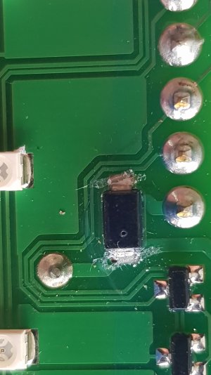
Something went pop.
- Thread starter KAM
- Start date
Saltram31
Well-Known Member
Easier to check the components with a multimeter. No guess work then.
Photo above looks like a diode. Resistors are fairly bombproof unless excessively over heated.
Photo above looks like a diode. Resistors are fairly bombproof unless excessively over heated.
KAM
Well-Known Member
Yes you're right. 59k one way open circuit the other.
penfold
Well-Known Member
Nothing wrong with it then, it's supposed to do that.
KAM
Well-Known Member
is 59K ok.
penfold
Well-Known Member
A bit leaky but not abysmal. measure the other one for comparison.
Boater Sam
Well-Known Member
That pin soldered joint next to it definitely needs reflowing!One of the resistors has blown. There's a small hole in it and it's open circuit. How do I tell what the resistance was. Are they identified by dimensions. There's another on the board which has the same dimensions.
A bit leaky but not abysmal. measure the other one for comparison.
[194224]
...
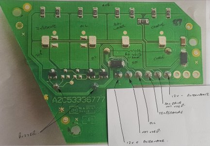
It's because the circuit diagram has incandescent lamps as indicators, hence the symbol for the lamp itself. The actual panel has LEDs so they require series resistors to drop the voltage across them to something in the order of 2-3V, not the 12V for the normal lamps. It appears that each LED has two 620Ω in parallel giving a series resistance of 310Ω which is not untypical. If one of those failed then everything should still work but the affected indicator would glow less brightly than its mates........... I was just wondering why there are more components than shown on the circuit diagram........................................................
I would expect to see a zener diode in the circuit for the charge lamp.
Last edited:
KAM
Well-Known Member
penfold
Well-Known Member
Sorry; brainfart time, that is actually broken. Double check of the other similar diode will confirm or deny.Yes you're right. 59k one way open circuit the other.
In the first instance I do find size is the easiest first step to identifying surface mount components, so a vernier caliper does become very important.One of the resistors has blown. There's a small hole in it and it's open circuit. How do I tell what the resistance was. Are they identified by dimensions. There's another on the board which has the same dimensions.
KAM
Well-Known Member
Both of the bigger diodes read 10k now. The earlier reading was wrong. Difficult to get a reliable reading through the coating.
[194224]
...
I'm pretty sure the connection marked 12V - Alternator is the charge connection to the alternator, presumably to the field coil.
".....Both of the bigger diodes read 10k now..." in both polarities?
".....Both of the bigger diodes read 10k now..." in both polarities?
KAM
Well-Known Member
It goes to the voltage sensing terminal labelled R on the alternator.
Both diodes are10k one way open circuit the other. Voltage drop on the diode tester was 0.58v which would seem to be satisfactory.
Both diodes are10k one way open circuit the other. Voltage drop on the diode tester was 0.58v which would seem to be satisfactory.
Last edited:
VicS
Well-Known Member
It the excitation resistor then ITYWF it'll be something in the range 33 to 50 ohms.It goes to the voltage sensing terminal labelled R on the alternator.
Both diodes are10k one way open circuit the other.
Without it the alternator wont start to generate. but every thing else should work OK... I'm surprised you blew it by shorting it to earth though.
FWIW here is the schematic of the later type of Yanmar panel as used on JH engines with the resistor shown near bottom right.
Attachments
KAM
Well-Known Member
The monitor board doesent seem to be associated with charging. With the board unplugged the alternator was producing 20 amps
[194224]
...
Yes that is indeed what it is but in this case it appears to be a self exciting alternator so the excitation resistor would only come into play if the residual magnetism in the alternator were to collapse. I had a Delco like that.It the excitation resistor then ITYWF it'll be something in the range 33 to 50 ohms.
KAM
Well-Known Member
I put 12v on the board today. The alarm circuits seem to be working OK. I haven't tested the charge light yet as I'm still not sure how it works. It's connected to the L and R terminals of the alternator. Presumably these have 12v when charging or maybe only when not charging. Can't quite see how this puts the warning light off. I'm sure someone out there can explain. Still unclear where the pop came from. The 3 amp fuse looked intact. It's one of those car fuses with a very clear indication. Just wondering if whilst fault finding I activated the stop solenoid which makes a similar sound.
Boater Sam
Well-Known Member
The warning light goes out when the alternator is charging because it has then 12v on both sides so no circuit.I put 12v on the board today. The alarm circuits seem to be working OK. I haven't tested the charge light yet as I'm still not sure how it works. It's connected to the L and R terminals of the alternator. Presumably these have 12v when charging or maybe only when not charging. Can't quite see how this puts the warning light off. I'm sure someone out there can explain. Still unclear where the pop came from. The 3 amp fuse looked intact. It's one of those car fuses with a very clear indication. Just wondering if whilst fault finding I activated the stop solenoid which makes a similar sound.
KAM
Well-Known Member
So grounding the charge connection on the panel should put the light on.
Boater Sam
Well-Known Member
Grounding the wire from the alternator with the ignition on, yes, it should. Running the engine then should put that wire to 12v because the alternator is producing 12v, and the light should then go out, no negative, just positive both sides.So grounding the charge connection on the panel should put the light on.


