Renogy 3000w inverter UK RCD?

Janinna2

New member
Joined
7 Nov 2019
Messages
7
Visit site
I'm seeing conflicting information about grounding inverters and RCD connections to ground on boats.

I appreciate the U.S system and advice is different to Europe so I am looking for U.K advice.

Renogy in their manual for a 3000w (and 2000w inverter) say that if you use an RCD on the outgoing side of their inverter (so the 240v AC coming out) then the neutral and ground should be joined.

When I asked an advisor if this was correct they said we don't advise using an RCD on the output. I pointed out that comment was incorrect given their instruction manual.

So now I am waiting for a more detailed response. But I have seen elsewhere that others have had conflicting errors in Renogy manuals.

So, I have a couple of fairly straightforward questions

Current practice for using an inverter and RCD in the UK on a GRP boat.

1. Should the ground of the metal casing of an inverter have a ground cable connecting direct to the Anode?

2. If an RCD is fitted on the 240vac outlet of the inverter should the earth have a connection back to the anode?

3. Should the neutral also be linked back to the Anode?

4. If an additional RCD were to be used that comes from the shore power cable to the inverter input (the Renogy 3000w inverter has an automatic transfer switch to accept shore power) should the earth bus bar in that RCD have a ground to the anode.


And all the questions above need to consider that the negative from Batteries on board also connect to the anode as does the engine block.


Basically I am looking for clear information on correct method of giving fault protection to AC and DC where they share a common ground at the anode?
 

PaulRainbow

Well-known member
Joined
16 May 2016
Messages
16,829
Location
Suffolk
Visit site
I'm seeing conflicting information about grounding inverters and RCD connections to ground on boats.

I appreciate the U.S system and advice is different to Europe so I am looking for U.K advice.

I'm not familiar with the Renogy inverters, so cannot comment on them specifically, but......
Renogy in their manual for a 3000w (and 2000w inverter) say that if you use an RCD on the outgoing side of their inverter (so the 240v AC coming out) then the neutral and ground should be joined.

When I asked an advisor if this was correct they said we don't advise using an RCD on the output. I pointed out that comment was incorrect given their instruction manual.
It is a requirement under current regs that an RCD is fitted to all AC power sources. Neutral and ground would normally be bonded at source, then an RCD/RCBO fitted (double pole).
So now I am waiting for a more detailed response. But I have seen elsewhere that others have had conflicting errors in Renogy manuals.

So, I have a couple of fairly straightforward questions

Current practice for using an inverter and RCD in the UK on a GRP boat.

1. Should the ground of the metal casing of an inverter have a ground cable connecting direct to the Anode?

2. If an RCD is fitted on the 240vac outlet of the inverter should the earth have a connection back to the anode?
All protective Earths should be connected together, typically on a busbar. Then, a single connection to the water, this is through the hull of a metal boat, the ground plane (if fitted) or an anode.
3. Should the neutral also be linked back to the Anode?
Absolutely not, neutral/Earth bonding must be done at the power source.
4. If an additional RCD were to be used that comes from the shore power cable to the inverter input (the Renogy 3000w inverter has an automatic transfer switch to accept shore power) should the earth bus bar in that RCD have a ground to the anode.
There must be a double pole circuit breaker on the incoming shore power, as close to the inlet as practical. The current ISO states:


A manually reset trip-free circuit breaker shall be installed within 0,5 m of the source of power
or, if impractical, the conductor from the source of power to the panel board circuit breaker shall be
contained within a protective covering, such as a junction box, control box, enclosed panel board or within
conduit or cable trunking or equivalent protective covering. If the location of the main shore power inlet
circuit breaker exceeds 3 m from the shore power inlet connection or the electrical attachment point of a
permanently installed shore power cable, additional circuit breakers shall be provided within 3 m of the
inlet or attachment point to the electrical system in the craft, measured along the conductor.

That could also be an RCBO
And all the questions above need to consider that the negative from Batteries on board also connect to the anode as does the engine block.
Nothing to worry about here, the PE is not a current conductor. If any current passes along it the RCD will trip.
Basically I am looking for clear information on correct method of giving fault protection to AC and DC where they share a common ground at the anode?
Again, the common Earth at the anode is of no consequence.

By the way, there should be a galvanic isolator or isolation transformer between the shore power inlet and the shore power system. You may not have one of these if the current system has no Earth connection to the water, if not, fit one.
 
Last edited:

Janinna2

New member
Joined
7 Nov 2019
Messages
7
Visit site
I would all ways go with what the origional manual instructs.

RCD's RCBO'S are a pain in the arse sometimes!
The problem is it appears the manual maybe wrong and I'm not the first to encounter this. If you connected earth and neutral on an RCD normally in a domestic house situation it would trip. Yet this manual suggests doing just that. Or at least it's saying connect ground to neutral enroute to an RCD. Ground being the metal casing of the inverter box. I believe the correct way to do this would be direct connection of the ground (inverter casing) to the anode, earth bus bar in the RCD to the anode. All negative battery terminals grounded to anode.

There would be a question mark of would that induce galvanic corrosion when connected to shore power but I am really not bothered about that in the interim, just correct earthing bonding of AC and DC on a boat.

The Renogy manual seems to suggest to purposely introduce a residual current path out of the norm and so far they have not given an adequate answer. In fact the advisor was clueless.
 

PaulRainbow

Well-known member
Joined
16 May 2016
Messages
16,829
Location
Suffolk
Visit site
The problem is it appears the manual maybe wrong and I'm not the first to encounter this. If you connected earth and neutral on an RCD normally in a domestic house situation it would trip. Yet this manual suggests doing just that. Or at least it's saying connect ground to neutral enroute to an RCD. Ground being the metal casing of the inverter box. I believe the correct way to do this would be direct connection of the ground (inverter casing) to the anode, earth bus bar in the RCD to the anode. All negative battery terminals grounded to anode.

There would be a question mark of would that induce galvanic corrosion when connected to shore power but I am really not bothered about that in the interim, just correct earthing bonding of AC and DC on a boat.

The Renogy manual seems to suggest to purposely introduce a residual current path out of the norm and so far they have not given an adequate answer. In fact the advisor was clueless.
I already told you how to do it. You are in danger of causing serious problems, please get an electrician to do this for you.
 

PaulRainbow

Well-known member
Joined
16 May 2016
Messages
16,829
Location
Suffolk
Visit site
The problem is it appears the manual maybe wrong and I'm not the first to encounter this.

The manual doesn't look wrong to me, assuming this is it ?

https://www.renogy.com/content/RNG-INVT-3000-12V-P2/INVT-P2-Manual.pdf
If you connected earth and neutral on an RCD normally in a domestic house situation it would trip.

Domestic AC in the UK is already bonded at source, so you don't do it again.
Yet this manual suggests doing just that. Or at least it's saying connect ground to neutral enroute to an RCD.
Inverters or generators must have the Neutral and Earth bonded on a boat, this is done at source. If the equipment cannot be bonded, it has no place on a boat, IMO.
Ground being the metal casing of the inverter box.
No. Earth and Neutral are bonded at source.
I believe the correct way to do this would be direct connection of the ground (inverter casing) to the anode, earth bus bar in the RCD to the anode. All negative battery terminals grounded to anode.
No. You've totally ignored my advice in post #3

There is no Earth busbar in a RCD
There would be a question mark of would that induce galvanic corrosion when connected to shore power but I am really not bothered about that
Unless you fit the GI or IT i previously mentioned you certainly run the risk of galvanic corrosion when connected to shore power.
in the interim, just correct earthing bonding of AC and DC on a boat.
You only need to worry about AC Earthing for fitting the inverter. Having the DC negative also connected to the anode is irrelevant.
The Renogy manual seems to suggest to purposely introduce a residual current path out of the norm and so far they have not given an adequate answer. In fact the advisor was clueless.
Sorry, but you clearly have a poor understanding of how this works, so with respect, i will say again, get an electrician (marine) in to do this for you.
 

rogerthebodger

Well-known member
Joined
3 Nov 2001
Messages
13,427
Visit site
That is he issue There is conflicting info with regard to the connection of the protective earth for generators and inverters on boats mainly GRP boats

Mine is a steel boat and I am happy with how mine is connected but will not discuss it hear as I have been shouted down too many times in the past

As Paulrainbow says, better get a marine electrician to look at this,they will be familiar with the set up

I would rather use an Electrical Engineer rather then an electrician but that's just me
 

Alex_Blackwood

Well-known member
Joined
19 May 2003
Messages
1,779
Location
Fareham
Visit site
The manual doesn't look wrong to me, assuming this is it ?

https://www.renogy.com/content/RNG-INVT-3000-12V-P2/INVT-P2-Manual.pdf


Domestic AC in the UK is already bonded at source, so you don't do it again.

Inverters or generators must have the Neutral and Earth bonded on a boat, this is done at source. If the equipment cannot be bonded, it has no place on a boat, IMO.

No. Earth and Neutral are bonded at source.

No. You've totally ignored my advice in post #3

There is no Earth busbar in a RCD

Unless you fit the GI or IT i previously mentioned you certainly run the risk of galvanic corrosion when connected to shore power.

You only need to worry about AC Earthing for fitting the inverter. Having the DC negative also connected to the anode is irrelevant.

Sorry, but you clearly have a poor understanding of how this works, so with respect, i will say again, get an electrician (marine) in to do this for you.
To be blunt I would say "Complete lack off understanding" I don't mean to be unkind but as usual the OP is completely unsure there is no harm in seeking professional advice for this sort of installation. It could be a life saver!! I have years of electrical experience but am not afraid to seek help if unsure.
 
Joined
10 Nov 2021
Messages
85
Visit site
Taking a look at the manual you provided, i would not connect the ground (inverter chassis) to the negative of your system or the anode.

I am a electrician myself, had a 500 watt inverter installed, never connecrwed the ground to anything, no problems.

Took it out as it was killing my batteries.
 

PaulRainbow

Well-known member
Joined
16 May 2016
Messages
16,829
Location
Suffolk
Visit site
Taking a look at the manual you provided, i would not connect the ground (inverter chassis) to the negative of your system or the anode.

I am a electrician myself, had a 500 watt inverter installed, never connecrwed the ground to anything, no problems.

Took it out as it was killing my batteries.
Here we go, as usual with inverter installations....

Who installed the inverter, what make/model was it and was it a fixed installation ?
 

jakew009

Well-known member
Joined
29 May 2012
Messages
425
Visit site
@PaulRainbow deserves a medal for his patience with these threads.

Taking a look at the manual you provided, i would not connect the ground (inverter chassis) to the negative of your system or the anode.

I am a electrician myself, had a 500 watt inverter installed, never connecrwed the ground to anything, no problems.

Took it out as it was killing my batteries.

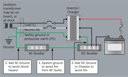
Consider what would happen if the DC 12v supply cable shorted to the inverter chassis. A huge DC current would try to return to the battery via the small 230V cpc which would likely melt / catch fire.

That’s why inverter manuals recommend a big fat cable from the inverter chassis ground back to the main earthing point.

Edit: the above is assuming you installed it as a ‘fixed’ system connected to your boats earthing system. If it’s isolated connected to just a single appliance it’s an irrelevance as Paul hints above.
 
Last edited:

Alex_Blackwood

Well-known member
Joined
19 May 2003
Messages
1,779
Location
Fareham
Visit site
@PaulRainbow deserves a medal for his patience with these threads.


Consider what would happen if the DC 12v supply cable shorted to the inverter chassis. A huge DC current would try to return to the battery via the small 230V cpc which would likely melt / catch fire.

That’s why inverter manuals recommend a big fat cable from the inverter chassis ground back to the main earthing point.

Edit: the above is assuming you installed it as a ‘fixed’ system connected to your boats earthing system. If it’s floating connected to just a single appliance it’s an irrelevance as Paul hints above.
Extracts from manual:-
Connect to 115V AC devices operating at higher than 15 A or distributed wiring with multiple A C outlets .Remove the two screws on the protective cover to access the terminals. Terminal layout (facing the front panel)z Left: Neutral (N)z Middle: Ground (G)z Right: Live (L)Note that Neutral and Ground are bonded inside.

While the inverter is equipped with a GFCI, it is recommended to install an external GFCI where you can manually test the circuit. (GFCI = RCD)

If available, the chassis ground lug should be connected to a ground point such as a vehicle chassis or boat grounding system. In fixed locations, connect the ground lug to earth ground. The connections to ground must be tight and against bare metal. Grounding is highly recommended for both when using the inverter in a mobile application, such as an RV, or in a building.


According to all that the Earth and Neutral are connected. The device chassis should be connected to an earthing point and an external RCD/RCBO is recommended.
 
Last edited:

jakew009

Well-known member
Joined
29 May 2012
Messages
425
Visit site
Extracts from manual:-
Connect to 115V AC devices operating at higher than 15 A or distributed wiring with multiple A C outlets .Remove the two screws on the protective cover to access the terminals. Terminal layout (facing the front panel)z Left: Neutral (N)z Middle: Ground (G)z Right: Live (L)Note that Neutral and Ground are bonded inside.

While the inverter is equipped with a GFCI, it is recommended to install an external GFCI where you can manually test the circuit. (GFCI = RCD)

If available, the chassis ground lug should be connected to a ground point such as a vehicle chassis or boat grounding system. In fixed locations, connect the ground lug to earth ground. The connections to ground must be tight and against bare metal. Grounding is highly recommended for both when using the inverter in a mobile application, such as an RV, or in a building.


According to all that the Earth and Neutral are connected. The device chassis should be connected to an earthing point and an external RCD/RCBO is recommended.

I think we are agreeing...

1712243617064.png

See this diagram taken from Grounding and Circuit Protection for Inverters and Battery Chargers - Blue Sea Systems

3. Install a DC grounding conductor sized not less than one size smaller than the DC positive conductor and have a capacity such that the DC positive fuse has an amperage rating not greater than 135% of the current rating of this grounding wire. As a practical matter, this wire will be much larger than the AC grounding conductor. This requirement is the latest addition to the standards when it was discovered that faults in the DC side of an inverter or charger could provide sustained high currents that could start a fire from overheating the AC grounding conductor.
 
Top