PaulRainbow
Well-Known Member
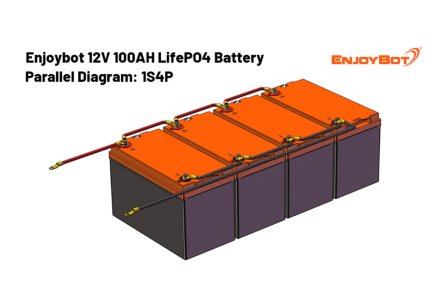
Except for 4 x the wiring, 4 x fuses, 4 x switches etc. But, as you have what you have...........Love me love I’m thick but I was under the assumption of 4 x 100ah batteries run in parallel were the same as a single 400ah battery.
Each battery positive connects to a class T or NH fuse, 150/160A. From the fuse to an isolator switch and then to a busbar.
Each battery negative connects to a busbar. If there is a battery monitor (which would be advisable) the batteries all connect to the shunt (if more than 2 connections, fit a busbar), then to the busbar and all loads and chargers connect to this busbar.
The positive cables all need to be exactly the same length between the batteries and the busbar. All negative cables also need to be exactly the same length.
DC-DC charger wiring only needs to be 10mm, with 60A fuses, one close to the starter battery and the other, a T class or NH fuse connected to the Lithium busbar.
The inverter needs to be connected to the busbar and should be wired with cables as specified by the manufacturer, fused at source.
Last edited:


")