wwaites
New Member
Hi all,
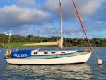
I am renewing the rigging on Hale Kai, a cutter-rigged Golden Hind 31. My plan is to use HMWPE rope (happy to discuss, perhaps in another thread, but that is not what this question is about).
I've been going around all of the chainplates and mast fittings, inspecting and measuring everything. It appears that all chainplates have holes to fit 3/8" (9.5mm) pins and all of the mast fittings have holes to fit 5/16" (7.9mm) pins. This seems very strange to me. I would have thought to use the same at both ends. No sense gratuitously creating a weak point aloft. Can you think of any reason why this may have been done? It was clearly intentional as it is perfectly consistent: the upper end of all stays and shrouds is smaller and the lower end is larger.
-w
")