Help please understanding switch panel

Stu66

New Member
Joined
28 Aug 2021
Messages
13
Visit site
Hi all,

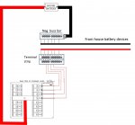
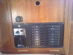
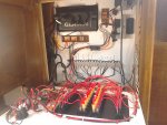
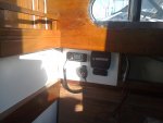
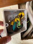
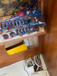
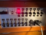
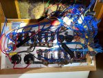
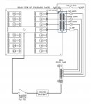
Here’s a pic of the switch panel wiring that came with an old (1976) boat I’ve just bought. I can see the positive feed coming to a bus bar on the panel, and positive wires running to one side of each of the switches.

All appliances are wired to a terminal strip (also mounted on the right hand side of the back of the switch panel), and from there to the other side of each switch / breaker. My question is what’s the polarity of these feed wires?

I’m confused as the new panel I bought to replace it, shows positive on one side of switch, and negative wires on the other (via a separate Neg buss bar).

Thanks
 

Attachments

  • 8B20B813-A40E-4419-893C-FEBEBABD6929.jpeg
    8B20B813-A40E-4419-893C-FEBEBABD6929.jpeg
    126.1 KB · Views: 87
  • E84B63F6-7A39-4F89-BA39-6CB0B0F8EFF0.jpeg
    E84B63F6-7A39-4F89-BA39-6CB0B0F8EFF0.jpeg
    209.3 KB · Views: 85
Last edited:
They will all be positive. as the +ve bus bar, switch, and breaker are all in series. before the appliance. The 'negative' will be the return from the appliance. There should be a negative bus bar somewhere if not on the panel for the return from the appliance unless they are randomly fed back to the battery -ve. From an easily accessible appliance trace the two wires the one from the switch/breaker is the positive and the other is the negative which should lead you to how the returns are wired.
 
They will all be positive. as the +ve bus bar, switch, and breaker are all in series. before the appliance. The 'negative' will be the return from the appliance. There should be a negative bus bar somewhere if not on the panel for the return from the appliance unless they are randomly fed back to the battery -ve. From an easily accessible appliance trace the two wires the one from the switch/breaker is the positive and the other is the negative which should lead you to how the returns are wired.

Thanks, I will trace back from a device and see where it leads me. I’m guessing there must be a negative buss bar somewhere as there are only 3 or 4 wires connected to the negative post on the battery.
 
Your new switch panel will just be the positive. Each switch will be wired one side and a terminal the other to connect to the circuit it is switching. Negative returns go to their own bus bar back to the negative terminal on the battery.

Just completed the same job on a similar age boat and ended up ripping everything out except for the lighting circuits and starting again. Positive from the load side of the isolator and negative from the common negative on the load side of the shunt for the battery monitor. Panel on a drop down lid and negative busbar made up from terminal strip with link wires on the bulkhead behind. All labeled with the name of the circuit corresponding with the name on the panel. Used just red and black Oceanflex tinned cable.

I was thinking something like this, and similar to yours, the terminal strip mounted on a board on the hull (or on the bulkhead), just behind the switch panel. Negative buss bar placed close to the battery & shunt.
 

Attachments

  • 740B1D15-53F4-436D-BC50-01568240D875.jpeg
    740B1D15-53F4-436D-BC50-01568240D875.jpeg
    203.7 KB · Views: 22
  • 2E229D08-C82A-4518-929F-5A089BE1ED66.jpeg
    2E229D08-C82A-4518-929F-5A089BE1ED66.jpeg
    201.8 KB · Views: 20
Last edited:
Your switches will, as mentioned above, control the +ve side of the circuits, however, switches with warning lights will have a -ve return for the warning lights. Because the current is so low, I'd expect them to be daisychained to one lead back the -ve busbar
 
Easier to show photos of the layout of the switch panel and wiring. First photo is the external view of the panel. 16 way fused made by Axon Components plus mimic for nav lights and blank to house switches for the automatic bilge pump and masthead light. Second is the back view showing the negative bus bar and back of instruments. The heavier cables coming in from the left link up to where the old switch panel was (third photo) which has the vhf, splitter, AIS, sockets and where all the existing lighting circuits came together. The feed from the battery comes in from the right, positive through an isolator. Eventually they will go back to new bus bars when I complete the wiring, but that is phase 2 when a new engine is going in. Wiring to the new batteries is temporary as in the last photo.

Obviously the details are specific to my installation but the principles I used might be useful. For example I grouped navigation under "GPS" on the switch panel - it came pre labeled and this circuit includes the chart plotter, AIS multiplexer and Garmin GPS. Below the plotter you can see a mini distribution panel made using Wago connectors - great little things. Also used them to bring all the cabin lighting circuits to one feed behind where the vhf etc is, for connecting mast cable wiring inside the boat and when adding extra lights into existing wires. everything works so far!
 

Attachments

  • IMG_20220426_144042.jpg
    IMG_20220426_144042.jpg
    878.6 KB · Views: 27
  • IMG_20220426_144226.jpg
    IMG_20220426_144226.jpg
    860.1 KB · Views: 29
  • IMG_20220319_190106.jpg
    IMG_20220319_190106.jpg
    718.8 KB · Views: 27
  • IMG_20220413_150908.jpg
    IMG_20220413_150908.jpg
    1,017.5 KB · Views: 24
I found the negative buss bar hiding in a junction box deep in the bilge… Are these normally placed somewhere behind the switch panel, or close to the battery & shunt?

I’m now thinking of re-running a correctly sized negative feed all the way from the battery to a buss bar placed on the bulkhead behind the panel.
 

Attachments

  • 9DE70D91-919C-480F-808D-7199CA1425D1.jpeg
    9DE70D91-919C-480F-808D-7199CA1425D1.jpeg
    181 KB · Views: 18
  • 59B52099-5687-4BF6-997D-885F75ED9156.jpeg
    59B52099-5687-4BF6-997D-885F75ED9156.jpeg
    271.6 KB · Views: 20
aS you can see my preference is to keep them close together. I did the same on a similar boat I rewired previously follow advice from Merlin eletrics who supplied the components and Taplin who made the panel for me. Last 2 boats I had were Bavarias and they had similar arrangements.
 
I found the negative buss bar hiding in a junction box deep in the bilge… Are these normally placed somewhere behind the switch panel, or close to the battery & shunt?
Place it wherever is convenient - I don't think there are any rules, just think about what's most practical.

That's not the worst installation I've ever seen, but I would want to improve it. Using green and yellow domestic wire for negative DC wiring would bug the heck out of me - I'm pretty sure the PO of my boat has used domestic wiring in a few places, and it's coming out when I get the chance.

I prefer busbars that can be properly screwed down, with a plastic cover over them, like these or these.

I would want to move it out of the bilges to keep it dry.

You can have more than one negative distribution point - one forward and another aft, for example, with them both led back to the battery negative with thickish cables.
 
Agree with using those types of bus bars for high current draws - I shall have them for the main battery and switch cabling but they are a bit OTT for low current draw downstream of the switches. I have also used the Blue Sea terminal blocks with jumpers as bus bars.
 
Top