Help Identifying Alternator Posts Yanmar 60 amp

Matwill

Member
Joined
1 Oct 2018
Messages
91
Location
Netherlands
Visit site
Hi Guys,

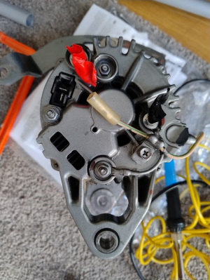
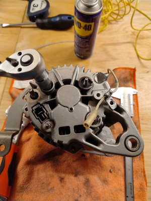
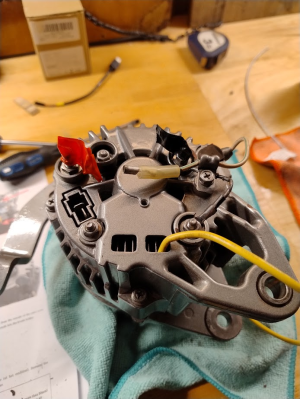
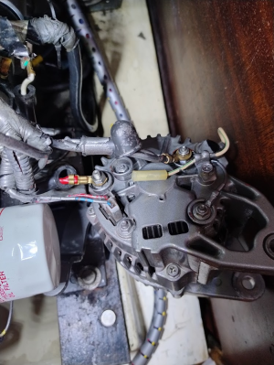
I'm in the process of fitting a sterling regulator to my 60 amp hitachi/yanmar alternator, I believe it is a LR160-741 - the problem is none of the posts are marked,

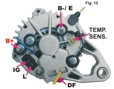
Can anyone help with what the posts are?

The posts I'm trying to identify are,

D+/61/L
B-
If there is a field wire here
B+

My assumption is the B+ is where the red cable/tape is connected and the B- is where the black cable/tape is connected.

I have also emailed Charles from Sterling

Thanks
Mathew

1708186346706.png
1708186361667.png
 

VicS

Well-known member
Joined
13 Jul 2002
Messages
48,208
Visit site
If you refer to the wiring diagram in the owner's manual for your engine you will be able to identify the connections by the colour coding of the wiring.

ITYWF of the connections to the two screw terminal posts red is battery positive and black is negative. Of the two plug in connections blue/black is the warning light and red/black the excitation connection. The tacho signal is a yellow wire
 

VicS

Well-known member
Joined
13 Jul 2002
Messages
48,208
Visit site
I assume you are fitting a Sterling "Advanced Digital Regulator"

Carefully follow the instructions to connect wires to each of the brushes and then to determine if the alternators uses positive or negative regulation and which of the two wires you will use as the field connection. (The unused one must be removed again or cut short and properly insulated.)

The instructions are very detailed . Read them carefully and be sure you understand them before proceeding.
 

VicS

Well-known member
Joined
13 Jul 2002
Messages
48,208
Visit site
Well done for finding those instructions although they ought to be available ( in English) directly from Sterling. Perhaps you'll get them when Charles Sterling replies to your email enquiry

I've bookmarked them for possible future reference but using an alternator to battery (AB) charger would be a lot simpler!
 

Matwill

Member
Joined
1 Oct 2018
Messages
91
Location
Netherlands
Visit site
Thanks for that, the thing missing from the official manual is this part that labels the B+, B-, IG and L

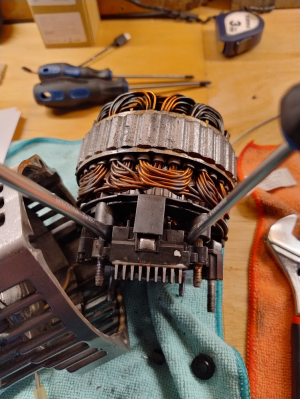
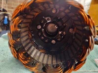
For future reference, also for anyone who tries this there are round plastic parts that will fall out of the inside of the case, these are different sizes and are used to guard the positive and negative terminals from shorting. The poles are different sizes so they can only go in one way. Its the same with all the plastic shielding on the back case nuts, they are designed to protect from accidental shorting, especially the case bolt/nut next to the B+

1708681217881.png

The other bit in the instructions that wasn't clear was where to pry the regulator housing up from

1708680786619.png

And that you can use your finger to push in the bushes to help guide the retaining wire through these 2 holes in the bushes - this photo shows the wire in place through the small hole in the bushes - also a 2mm wire wont fit through this hole, I used some plastic coated wire which was strong enough, I imagine if your bushes are more worn then this and the holes are no longer there, then you would need a stiffer piece of wire and a 2mm wire would probably be a good choice.


1708681056030.jpeg
 
Top