Charging starting battery from solar?

Made a simple diagram to connect the starting battery to the solar with a spare PWM controller I already have. Just wanted few opinions about it -if there is anything wrong
Thanks
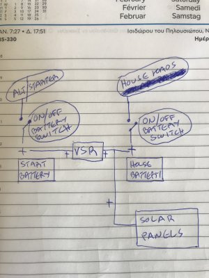
For the various reasons already stated i would not connect two controllers to the same panel.
I would obtain a second smaller solar panel and connect it via the pwm controller to the starting battery. 5 watts would be large enough

1739232832351.png
 
Thank you all for your time and valuable feedback. Seems like I ll have to either go with a small extra panel or with a VSR. As I feel somehow safe turning the battery switches off when leaving the boat, I would like to maintain this option…
What about doing the installation as in the diagram?
 

Attachments

  • 8A4D0CD3-D626-437C-BC5B-5241BCD67BDD.jpeg
    8A4D0CD3-D626-437C-BC5B-5241BCD67BDD.jpeg
    1.5 MB · Views: 21
A MPPT controller works by adjusting its input voltage (the voltage of the solar panel) to the optimal value where the panel can deliver the maximum power. It then converts this higher panel voltage to a lower voltage suitable for charging the battery.

A MPPT controller and a PWM controller will select similar output or battery voltages assuming the charge algorithm is similar; it is the input or solar panel voltage that is different. With a "12V" panel, a MPPT controller may be keeping the solar panel around 17-18V to extract the maximum power from the panel. With a high voltage panel, the input voltage may be 50V or more. A PWM cannot perform this voltage conversion, so the solar panel needs to be at a much lower voltage.

A single solar panel can only have one voltage at any particular instant so trying to implement both of these options simultaneously is problematic.
I have been trying to remain quiet on this. However the above is a load of total Ball ox, sorry! The solar panel will output a voltage depending on the ambient conditions. That is what the controller will see. The controller depending on type, will convert that voltage to an output. The voltage at the input terminals will not change! You can feed as many controllers, with in the load constraints, from a solar array as you want. If the solar panel array is rated at 100 watts that is the maximum you will get out of it. If you try and connect 150 watts something will give. Most likely the voltage from the panels will drop and the controllers will cut out or they will just not work to capacity. ( I am not sufficiently Au fait with these controllers to be 100% certain, therefore will try and refrain from spurious comments) It should of course go without saying that as well as a fuse protecting the panels and associate wiring, each controller should have a suitable fuse in the circuit.
Having said all that, I would concur with others who have suggested that a VSR is the way to go :)

mmmmmm Solar panel voltage is a near constant - its the amps output that changes with energy seen from sun.

Many panels are rated at 18,5v or more ... the controller of course then knocks that down to the required charge voltage .. amps are then based on the wattage panel is generating and what battery accepts.

VSR is fine for general charging - but isn't that a bit of an overkill item if just controlling solar to batts ? There are plenty of low power charge splitters with 'zero loss' from such as KEMO etc ...
But one factor is that the battery side of controller must always be seen by Solar controller - so any switching cannot switch off from battery completely.
I think personally - simplest is to just connect Solar to the starter battery alone (as long as you can start engine - then you can charge up all batterys from alternator) or get a Dual output controller ... lot cheaper than a VSR and it will look after both batterys ...
You try measuring the voltage from a solar panel and then partially shade it and see what happens to the voltage. Is it constant? :unsure: Voltage and Amps are interrelated.
Anyway what I was saying is, Noelex is mistaken.
 
Last edited:
Thank you all for your time and valuable feedback. Seems like I ll have to either go with a small extra panel or with a VSR. As I feel somehow safe turning the battery switches off when leaving the boat, I would like to maintain this option…
What about doing the installation as in the diagram?
The VSR is sensible addition because it ensures that your house battery will be automatically charged from the alternator when the engine is running without fiddling with any manual switches. It will slso mean tht the main solar panel will also be charging the Starter battery. All assuming , of course, that the negatives of both batteries are connected to form a common ground
It maybe worth fitting a switch in the VSR negative connection so that it can be disabled if necessary.
 
You try measuring the voltage from a solar panel and then partially shade it and see what happens to the voltage. Is it constant? :unsure: Voltage and Amps are interrelated.
Anyway what I was saying is, Noelex is mistaken.

The voltage will stay relatively steady until sufficient is shaded to prevent the cells from overcoming resistance .... if that was not true - then panels would not be working in 'low sun' situations ......
V and A are inter-related in WATTS ... and if you watch the output of panels as shade takes effect - the voltage stays relatively steady - but as watts output falls - amps fall of dramatically .. till that point that voltage cannot be sustained ....
 
Thank you all for your time and valuable feedback. Seems like I ll have to either go with a small extra panel or with a VSR. As I feel somehow safe turning the battery switches off when leaving the boat, I would like to maintain this option…
What about doing the installation as in the diagram?
This is correct. Put a fuse between the battery and the solar controller and between the batteries and the VSR, all as close to the battery as possible.
 
The solar panel will output a voltage depending on the ambient conditions. That is what the controller will see. The controller depending on type, will convert that voltage to an output. The voltage at the input terminals will not change!
A look at a typical solar panel output curve (see below)will show that we can measure the output of any solar panel at any voltage up to its Voc. Each line is for a fixed set of conditions. How is such a graph produced if the voltage of the solar panel fixed and cannot be altered?

The voltage of the solar panel is not fixed; it is dependent on the impedance of what it is connected to. By adjusting its input impedance, a MPPT controller alters the voltage of the solar panel. It does this to try and maintain the maximum output from the solar panel.

The label on the back of every solar panel even shows two significantly different voltage measurements produced under identical lighting (STC) conditions. Voc and Vmp. How is this possible if the voltage of the solar panel is fixed and only dependent on the lighting conditions as you claim?

If you don’t think an MPPT controller is tracking and optimising the solar panel voltage to maximise the output of the solar panel, what is it doing? How is the controller maximising the output? What is it adjusting to keep the panel at the maximum power point? What happens to the solar panel voltage if you don't use a controller and connect the solar panel directly to the battery with thick wire? Does the solar panel maintain its 18V when the battery is say 14V?

You will find with some thought that the idea that the solar panel is at one fixed immovable voltage for each lighting level does not make sense.

If the solar panel array is rated at 100 watts that is the maximum you will get out of it. If you try and connect 150 watts something will give.
A MPPT controller will typically extract more energy from a solar panel than a PWM controller, and slightly above the solar panel rating is possible in exceptional conditions. But I have certainly never indicated it is possible to extract 150W from a 100W panel.

IMG_7710.jpeg
 
Last edited:
This article on the basics of how MPPT work may help:

Basics of Maximum Power Point Tracking (MPPT) Solar Charge Controller

"The major principle of MPPT is to extract the maximum available power from PV module by making them operate at the most efficient voltage (maximum power point). That is to say:

MPPT checks output of PV module, compares it to battery voltage then fixes what is the best power that PV module can produce to charge the battery and converts it to the best voltage to get maximum current into battery."
 
Noelex is right however just few comments. A PWM controller in most circumstances ie large depleted battery and limited panel size and sunshine is a direct connection panel to battery.
The max voltage of a panel is determined by the number of cells typically about .4v all in series. The number of cells is chosen to give a voltage at no load max sun well above the voltage needed to put charge in to a 12v LA battery (14v) but with enough excess voltage capability that you can still get some charge into a battery at lower light poor angles to sun. Hence no load voltages of 18 to 20 v. Yes in ideal conditions of lots of sun and say a charging voltage of 13v (depleted battery) much power is wasted. The PWM aspect only comes in to play when it reckons the battery is full.
A solar panel has a power generating capability. But this depends on both the sun strength and angle to sun. (insolation) If we do not draw much current from a panel then the panel voltage remains high but power out remains low P= V x current . Similarly if we put a great load on the panel the voltage falls and we do not get best power out of the panel. We in effect choke it to death. However there is a best load option which will suck out the max power as a best compromise of voltage and current. This best compromise will depend on the insolation. (sunshine)
A PWM controller will often operate in a useful regime but there is no control over current and voltage it is not always optimum.
The MPPT controller uses what is effectively a variable transformer such that we can vary the load on the panel. ie suck more or less current so that voltage remains not at max but at a level still giving good power. This transformer is controlled by a microprocessor to constantly adjust the load while all the time converting to a voltage needed to charge the battery. Hence the name Maximum Power Point Tracking. ol'will
 
I want to achieve the same as the OP.: Charge both Lithium "house bank" and Acid starter+bow prop batteries from all sources: Sun, alternator, Mains charger. But I want to keep the "house system" separate from the starter one.
I already have a DC-DC charger that also has an input for the alternator and for mains.

Could it be done in such a way?

Thanks!


El system pt. 1.png
 
AIUI, there's no need for a switch between the MMPT and the house batteries. There's a significant risk of damage if it's turned off without isolating the solar panels. You do need a battery isolator switch, but I'd connect the solar system on the battery side of the isolator.

I'm no expert on LiFePO batteries, but I think I'd want an isolator for them, too. Personally, I'd wire automatic bilge pumps on a separate off-auto-on switch direct to the batteries, with their own fuse, obviously, but there are arguments for and against that idea.

As I mentioned earlier .... Solar controllers need battery connected first and not switched off - before solar connected.
 
I want to achieve the same as the OP.: Charge both Lithium "house bank" and Acid starter+bow prop batteries from all sources: Sun, alternator, Mains charger. But I want to keep the "house system" separate from the starter one.
I already have a DC-DC charger that also has an input for the alternator and for mains.

Could it be done in such a way?

Thanks!


View attachment 189509
Connect all charging sources to the start battery and the DC-DC charger will look after the Lithiums. Then fit a VSR between the start and bow batteries.
 
My Eperver twin battery job wants battery one connected first. I have a feeling I damaged it by getting that wrong during a battery upgrade, as it doesn't seem to be working anywhere nearly as well now.

I'm considering replacing it with a single battery job and a VSR, but I'm not sure how that would fit with having one big bank that starts the port engine and runs the domestics, and a smaller one that does nothing but start the starboard one, plus, of course, a separate alternator for each bank.
 
Top