Inclination
New Member
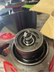
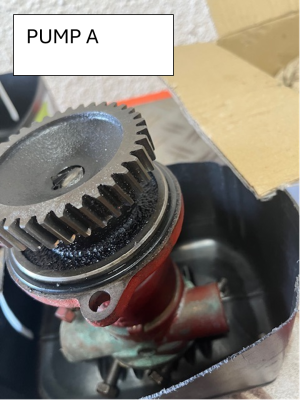
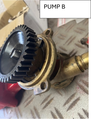
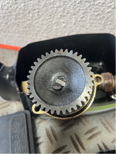
My 1983 DV36 has been reliable for 15 years. It’s fitted with a heat exchanger, with the coolant circulation pump mounted directly behind the raw water pump. A shaft connects these two pumps. Late last year we discovered a coolant leak which lead to the pumps being removed. While the leak was an easy fix, we found the pump shaft had sheared, resulting in highly reduced coolant flow. While waiting for a new replacement raw water pump and shaft a refurbished pump was installed. These got us through the summer season ( live in NZ), last week we fitted the brand new raw pump and shaft. It lasted. Less than an hour before the engine started to overheat, cruising at 2500rpm. Further investigation showed the connecting shaft had sheared completely, resulting in no coolant being circulated. Looking at the refurbished pump we used for 2 months over summer it too is showing signs of wear on the connecting shaft. So in the space of just 3 months, 3 shafts have failed. My mechanic, a trained bukh technician has checked all tolerances and can identify no reason for these failures. Bukh themselves say they have no experience of this. Has anyone experienced pump shaft failures like this on the dv36? Anyone got any clues / ideas, I’m at loss and unless a cause can be found I’ll be forced to re-power, which will be such a shame, I love this engine, but can it be saved?