Bilge pump wiring to control panel

Jokani

Well-Known Member
Joined
21 May 2014
Messages
849
Visit site
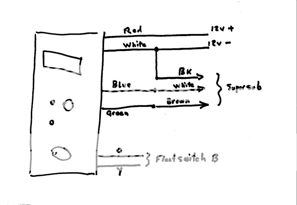
I hope to wire a Whale Supersub to a pump control panel

The panel is expecting a separate float switch, but the supersub has an integral switch.

I'm unsure where the 3 pump wires need to go.

Please would someone help me out.

whale-supersub-panel-wiring-diagram.png
 
Since the panel expects a dumb pump ( no float switch) you would use the "manual" connection to the pump.
So...
Pump white to panel blue
Pump black to panel white
Pump brown not used since the auto/manual/off function is part of the panel and attached float switch.
 
Hello

It took me a while to realise that the switch action was counter intuitive, so Manual is at the opposite side of the switch to what you first think because it pivots and vice versa for the Automatic.

The switch needs a positive feed cable from the battery and instructions usually ask for a fuse in this cable. On 12v DC this is expected to be Red and goes to a central point on the switch.


The Brown cable from the pump is matched to the Automatic side of the switch, see above for how switch pivots between Auto and Manual.

The White cable is matched to the Manual side of the switch and the Black (Negative) goes direct to the battery. Hoping this makes sense.
 
Hoping to clarify

If the Manual switch is a press and hold, for activation, like mine, it will not power the Pump unless it is held on, I think.

Hence using the Automatic side to act as on/off for power supply to the pump so it can do its automatic thing. Assuming that, like mine, the Auto side stays on when you press it.

Cheers
 
I don't think anyone can give a meaningful answer, as there's no clues about what the various panel wires are connected to. Frankly, the panel isn't necessary for your pump - why not just wire it to a permanent fused supply and let it sort itself out automatically? Isn't that why you bought it?
 
This is my working out from the combined advice so far, and then a bit of guess work:

Pump + (Brown) - Panel (Blue) - This is the auto function
Pump - (Black) - Panel (White) - Just negative to negative
Pump (White) - Panel (Green at a guess) - Red is direct feed to battery and does not connect to the pump, green is the only other wire of the 4 left

Correct?
 
I don't think anyone can give a meaningful answer, as there's no clues about what the various panel wires are connected to. Frankly, the panel isn't necessary for your pump - why not just wire it to a permanent fused supply and let it sort itself out automatically? Isn't that why you bought it?
i wired mine to a 3 way switch
on
off
auto
 
Dumb on my part Sailorman, I fitted the panel and pump and left the wiring until last.

I would hate to leave the panel unconnected or even worse remove it and leave a hole.

If there is no way to figure it out then I guess I'm stuck.

Next time I'll figure out the wiring before I cut the holes. I liked the panel as you could wire up a second switch as a high water alarm.
why a high water alarm
the pump should have pumped out by that time
all you may need to know is that the pump has run or running
 
If I was to try it this would be my best guess:

Pump + (Brown) - Panel (Blue) - This is the auto function
Pump - (Black) - Panel (White) - Just negative to negative
Pump (White) - Panel (Green at a guess) - Red is direct feed to battery and does not connect to the pump, green is the only other wire of the 4 left
 
This is my working out from the combined advice so far, and then a bit of guess work:

Pump + (Brown) - Panel (Blue) - This is the auto function
Pump - (Black) - Panel (White) - Just negative to negative
Pump (White) - Panel (Green at a guess) - Red is direct feed to battery and does not connect to the pump, green is the only other wire of the 4 left

Correct?

Swap green and blue. and dump the float switch between green and blue (it is provided by the pump. Or use that float switch and wire as I said above.

The panel will output +12V on blue when the switch is on manual and open circuit otherwise. The panel will output +12V on green when the switch is on auto so, if the float switch connects then the pump runs.
 
why a high water alarm
the pump should have pumped out by that time

Right - should have. If it hasn't, you want to know about it, hence the high water alarm.

When I was on a school boat that flooded, we only knew about it because luckily the gas alarm started making a funny noise when its sensor shorted out. The water at that point was about level with the bunks.

Pete
 
On my boat it would be over the sole :)

So was this - about 18" over the sole :)

The gas alarm was probably poorly located, but I'm still grateful to it for making noise rather than dying silently. There was no hood, so we had the hatch pulled across to keep spray out on a slightly lumpy day, hence not noticing the cabin filling up.

Pete
 
Connect the power as per instruction to the panel permanent live supply via an appropriate inline fuse, with a multi meter or test lamp check which terminal or fly lead is live when switched to auto position, connect that terminal to the brown cable on the Supersub. Now check which terminal or fly lead is live when switched to manual and connect that to the white cable on the Supersub. Black cable on the Supersub to negative bus or battery -
 
Swap green and blue. and dump the float switch between green and blue (it is provided by the pump. Or use that float switch and wire as I said above.

The panel will output +12V on blue when the switch is on manual and open circuit otherwise. The panel will output +12V on green when the switch is on auto so, if the float switch connects then the pump runs.

Discard float switch A and wire like this:


Scan_20150617.jpg
 
Blue is manual and green is the auto output... I. E when switch set to manual the blue will be raised to 12v and run the pump and when switch set to auto, the green will be raised to 12v and power the pump through the float switch.

Your pump therefore needs the blue manual wire from the switch connected to the white wire on the Supersub.
For auto operation, connecting the switch green wire to the supersub brown should give a 12v supply to the pump and put it into auto mode. .

That's my take on it whilst writing from the phone and trying to remember the diagrams. .. will double check in the morning but it should be possible.

For auto operation you will
 
Top