robertager1962
Well-Known Member
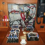
Currently in lock down in Northern Spain I have been working on some projects, one of which is the re-wiring of the instrument panel. I am planning on using buzz bars for both negative and positive supplies but wonder if there is an alternative to crimping eyes onto the cable. Googling this just seems to bring up crimping. As usual any thoughts gratefully received.