Adverc voltage adjustment

Sea_Sense

New member
Joined
6 Apr 2004
Messages
24
Location
Kent
Visit site
Hi, I would appreciate some advice on an adverc issue.

I have two battery banks split with a diode. The engine battery is at the back of the boat and the other battery bank is at the front of the boat.

The voltage reduction over the 7 metre run is about half a volt to the batteries in the front of the boat. My adverc is increasing the voltage to 15.2 to make sure my battery bank at the front of the boat is charging at 14.4 v but this mean the engine battery is receiving 15 volts when being charged.

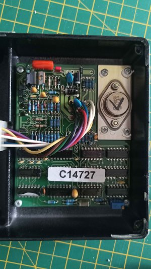
I saw on a previous thread I can turn the voltage down within adverc. I believe I have to use a flat screw driver and turn the blue capacitor thingy in the bottom right of the photo.

Am I right in my assumptions? And which way do I turn it and roughly how many turns?

Thanks in advance for any advice
 

Attachments

  • IMG_2665.jpeg
    IMG_2665.jpeg
    956.9 KB · Views: 15

Boater Sam

Well-known member
Joined
14 Mar 2020
Messages
1,400
Location
Philippines and Thailand
Visit site
That looks to be a multiturn potentiometer not a capacitor. It would normally be a 10 turn, adjust it a little bit at a time.
I have no idea which way will reduce the voltage, try it a bit and see.
It would be better if you got rid of the diode splitter by using a VSR or even a simple split charge relay then both your batteries could be charged at the correct voltage
 

VicS

Well-known member
Joined
13 Jul 2002
Messages
48,339
Visit site
That looks to be a multiturn potentiometer not a capacitor. It would normally be a 10 turn, adjust it a little bit at a time.
I have no idea which way will reduce the voltage, try it a bit and see.
It would be better if you got rid of the diode splitter by using a VSR or even a simple split charge relay then both your batteries could be charged at the correct voltage
I agree with what you say about the multi-turn pot.
However changing from a diode splitter to a vsr will not solve the problem. The voltage drop across the two sides of the diode splitter will be the same. Sea-Sense's problem is caused by volts drop in the 7m long wiring.
It could be halved by doubling the cross section area of the wiring.
It could be eliminated by putting a suitably rated silicon diode in the circuit between the diode splitter and the engine start battery but the snag with that will be that as the battery in the bow becomes charged and the current reduces the volts drop will fall with the result that the Adverc will reduce the alternator output voltage to the point where the engine start battery will not be charging properly although by then it should also be nearing full charge.
 

William_H

Well-known member
Joined
28 Jul 2003
Messages
13,765
Location
West Australia
Visit site
Presumably the adverc is battery sensing on the front (large house) battery at the battery. The volt drop of quoted half a volt would only be when front battery is taking a large charge current. The volt drop and hence charging voltage will drop as current falls due to less volt drop in charging wires. However this may still be too much for too long for the engine battery.
OP does not specify the type of diode splitter and hence what volt drop it presents.
The suggestion of a diode in series with the diode of the splitter will indeed reduce charge voltage to engine battery but as said will leave engine battery less than fully charged.
I think either introduce a series resistance (not diode) in the line to the start battery from diode splitter to reduce current but perhaps best approach would be to move the diode splitter to the front so that charge voltage less volt drop appears at front and volt drop at high charge current is shared by both batteries. ie take the feed to the engine battery from a point voltage wise near the front battery.
Of course more heavy wiring to front battery will reduce the effect. ol'will
 

Sea_Sense

New member
Joined
6 Apr 2004
Messages
24
Location
Kent
Visit site
thanks for the advice - the split charger is a Sterling Power Split Charge Diode D90A2. I had a thought, rather than moving the split charger could I increase the length of the positive battery cable from the split charger to the engine battery? So run in a 6 metre loop and create a similar voltage drop to my leisure batteries?
 
Last edited:

B27

Well-known member
Joined
26 Jul 2023
Messages
1,478
Visit site
The voltage drop in a long run will vary with the current.
The voltage drop in a diode will vary with current.
There is no way to make things compensate fully over a range of currents.

However, what you need is to have things 'near enough' so your house battery gets enough charge and your engine battery doesn't get so overcharged that it has a very short life.

You could consider an EFB or AGM engine battery which might be more resilient to over changing?
You may need to be careful with some things like certain LED lights which will get hot or die at 15V.
Some non-automotive or cheap LEDs really only want 12.0 Volts for instance.

The ADverc may be sensing the battery volts, not sure if it only compensates for the drop in the + cable, or senses the - terminal of the battery too?
Ideally one would not tolerate such voltage drops except perhaps for short periods of peak current.
 

Boater Sam

Well-known member
Joined
14 Mar 2020
Messages
1,400
Location
Philippines and Thailand
Visit site
The voltage drop in a long run will vary with the current.
The voltage drop in a diode will vary with current.
There is no way to make things compensate fully over a range of currents.

However, what you need is to have things 'near enough' so your house battery gets enough charge and your engine battery doesn't get so overcharged that it has a very short life.

You could consider an EFB or AGM engine battery which might be more resilient to over changing?
You may need to be careful with some things like certain LED lights which will get hot or die at 15V.
Some non-automotive or cheap LEDs really only want 12.0 Volts for instance.

The ADverc may be sensing the battery volts, not sure if it only compensates for the drop in the + cable, or senses the - terminal of the battery too?
Ideally one would not tolerate such voltage drops except perhaps for short periods of peak current.
The voltage drop across the split charge diose is a constant no matter what current is passing.
The voltage drop in the cable to the remote battery will reduce as the charge current reduces as the batteries take up charge. It will be zero when the current is zero, i.e. when the battery is fully charged.
The only problem is that when the remote battery is drawing a heavy charge current the engine battery will be at too high a voltage. This is solvable by putting a VSR sensing the remote battery voltage so that the engine battery only charges after the remote battery is reaching a full charge.
 

Sea_Sense

New member
Joined
6 Apr 2004
Messages
24
Location
Kent
Visit site
The voltage drop in a long run will vary with the current.
The voltage drop in a diode will vary with current.
There is no way to make things compensate fully over a range of currents.

However, what you need is to have things 'near enough' so your house battery gets enough charge and your engine battery doesn't get so overcharged that it has a very short life.

You could consider an EFB or AGM engine battery which might be more resilient to over changing?
You may need to be careful with some things like certain LED lights which will get hot or die at 15V.
Some non-automotive or cheap LEDs really only want 12.0 Volts for instance.

The ADverc may be sensing the battery volts, not sure if it only compensates for the drop in the + cable, or senses the - terminal of the battery too?
Ideally one would not tolerate such voltage drops except perhaps for short periods of peak current.
My understanding from the wiring diagram it only senses the drop on the + cable from the splitter to the battery terminal. So when it starts sensing at 14v it is pumping in 15.2 volt at the splitter and 14.4 is received at the leisure battery bank but unfortunately that means it receives 15 v at the engine battery. This afternoon I tried extending the engine battery cables on the + side by 6 metres and about 4 metres on the _- side which reduced the engine battery charging to 15 volts. However that seems an inefficient way of operating. I wonder if I can find 12 v resistor to reduce the engine battery charge by half a volt or so …… time for google ….
 

B27

Well-known member
Joined
26 Jul 2023
Messages
1,478
Visit site
When you've just started the engine, the engine battery will want say 10A for a while to charge it.
When your engine has been running for half and hour, the battery will only take a fraction of an amp.
So there is no one value of resistance which will do the job.

Conversely, if your house batteries are well charged, the current into them will drop, so the cable drop will be less and the Adverc will back off the alternator voltage to maintain the same battery voltage.

None of this may matter if you don't motor hundreds of hours a year.

These days solar charging means alternator charging is less important for many people including me.
What you have is not IMHO 'optimal' but is it a 'real problem' to you?
If so then maybe take a step back and look at the wider system on your boat. Including how you use it and what your charging needs really are.
There are many different things you could do, which is best will depend on you.
 
Top