anoccasionalyachtsman
Well-Known Member
Inspired by Spyro's thread on doing the same to a Raymarine pilot, I thought I'd do likewise unto my Simrad. This is a TP32, but I believe that the TP10 and 22 share the same casing.
You'll need one of these.

From https://www.ebay.co.uk/itm/12V-4CH-...e=STRK:MEBIDX:IT&_trksid=p2057872.m2749.l2648
Which contains this.

Which, if it were to fit without risk of fouling, would be lovely. Unfortunately the four black relays and the two large capacitors risk fouling the rubber buffer which is free to move with the actuator rod. It's all just a bit close for my liking. So we need to do some juggling. De-solder the terminal blocks and the capacitors, then trim off the redundant edge of the circuit board.
Remove the jumper which you'll find on the three pins bottom right in the pic above.
Before you throw that strip away, use a fibre tip to mark the pcb ABC at the holes to which the terminal block was soldered.
I should add that as I was finishing the job I noticed that the aerial's soldered joint to that little stand-up pcb was loose. Bit of a dry joint, worth checking.

Note that where the capacitors sat there are two half-shaded circles. That white bit is where the stripe on the capacitor should be. The capacitors are 16V µ470 available here
https://www.ebay.co.uk/itm/Radial-Electrolytic-Capacitors-Various-Value-and-Voltage/111047335596?ssPageName=STRK%3AMEBIDX%3AIT&var=410231617696&_trksid=p2057872.m2749.l2648
or, the first person to send me a pm will get the two spares I have here.
Insulate and bend the legs, then solder to the board (noting the stripe's orientation) as you can just about make out in the pic near the bottom (forgot to take one at this stage).

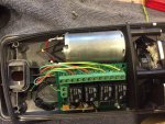
Now, armed with the Simrad workshop manual (which seems to have disappeared from Simrad's site so pm me an email address for a copy), open up the casing - noting that a small ss rod lives in a hole near the motor's drive gear and will fall out and could confuse you horribly - and then remove the second part of the casing which houses the main pcb. Before you do anything else use some masking tape to hold the fluxgate pod to the pcb because you really don't want to damage those wires. Take the gasket off and give it a wash to in warm water to get the salt out.
I used the wires from an 8 core alarm cable to connect to the four switches (the tiller end pair of legs connect to one switch contact, the boat mount end pair connect to the other). So, for example, the green wire is connected to the right hand upper leg, the brown to the left lower.

Note the red circles. I glued the wires down onto the main pcb so that the two leds didn't get obscured, and that no wires could get trapped between the sockets in the top of the housing (below) and the two circled pins above.

I made a 6mm hole at the bottom of the main pcb housing, and tried to find a grommet that would fit it to no avail. I freely admit that if I'd known that someone would ask me to write this I'd have made a better job of the silicon seal. Messy, but it works.
Next is to 'steal' 12v from the supply to the board - I just sliced off the insulation, staggering the two so that there's little chance of them touching each other. I also used slightly thicker wire for the power connection. Cover the joins with insulating tape.

Now you need to do some thinking and measuring with the remote control pcb temporarily fitted in its final location.
Button A on the keyfob controls the relay at the 12v supply end of the board (bottom in the pic below) and I chose that to be 'port'. I then made B = stbd, C = Tack and D = Standby.
If you choose to do the same, then looking at the pic below the Standby relay is at the top, then Tack, Starboard and Port at the bottom.
Cut and strip the wires to appropriate lengths so as to avoid too much bunching when it's all back together.
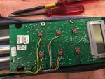
You'll be connecting to A and B that you marked on the PCB for each of the relays - the C holes aren't used.
Last bit of soldering is the two power wires into the two power supply holes at the bottom of the PCB. Red to +ve, black to -ve.
Now glue it down (CT1 pu glue worked for me).

Tuck the wires around that post so that they too don't get squashed when the opposing pillar comes down to meet it.
Lastly, I threaded the aerial wire up the side of the now replaced main pcb casing, and tacked it down with more CT1. It's the black wire that you may need to squint a bit to see.

And here it is before putting the lid back on. Take your time re-seating the long gasket on the bottom half, I went round and round gently tapping it lightly until it all sat down perfectly - except at one point where that diagonal rib bottom right won't let it sit quite correctly. Before you finally close it, squeeze some silicon grease onto the actuator rod a suggested in the service manual.

And don't forget that odd little stainless stiffening rod. I'd love to know why it's the length that it is. Bizarre.
A couple of notes.
I've just realised that if you solder your pairs of wires to the remote control pcb first then it'd be a lot easier to get the lengths right when you solder to the main pcb.
If before you finish the conversion you decide that you want to test the pilot with the case open to remind yourself how long a press you need to give the port or starboard button to get a 10 degree course change - press the micro switch on the main pcb. Don't do what I did and press the rubber button on the case - it's not touching the switch and won't work. Thinking you've somehow wrecked the pcb is not a good thing, no matter how much you later giggle at your own stupidity.
You'll need one of these.
From https://www.ebay.co.uk/itm/12V-4CH-...e=STRK:MEBIDX:IT&_trksid=p2057872.m2749.l2648
Which contains this.
Which, if it were to fit without risk of fouling, would be lovely. Unfortunately the four black relays and the two large capacitors risk fouling the rubber buffer which is free to move with the actuator rod. It's all just a bit close for my liking. So we need to do some juggling. De-solder the terminal blocks and the capacitors, then trim off the redundant edge of the circuit board.
Remove the jumper which you'll find on the three pins bottom right in the pic above.
Before you throw that strip away, use a fibre tip to mark the pcb ABC at the holes to which the terminal block was soldered.
I should add that as I was finishing the job I noticed that the aerial's soldered joint to that little stand-up pcb was loose. Bit of a dry joint, worth checking.
Note that where the capacitors sat there are two half-shaded circles. That white bit is where the stripe on the capacitor should be. The capacitors are 16V µ470 available here
https://www.ebay.co.uk/itm/Radial-Electrolytic-Capacitors-Various-Value-and-Voltage/111047335596?ssPageName=STRK%3AMEBIDX%3AIT&var=410231617696&_trksid=p2057872.m2749.l2648
or, the first person to send me a pm will get the two spares I have here.
Insulate and bend the legs, then solder to the board (noting the stripe's orientation) as you can just about make out in the pic near the bottom (forgot to take one at this stage).
Now, armed with the Simrad workshop manual (which seems to have disappeared from Simrad's site so pm me an email address for a copy), open up the casing - noting that a small ss rod lives in a hole near the motor's drive gear and will fall out and could confuse you horribly - and then remove the second part of the casing which houses the main pcb. Before you do anything else use some masking tape to hold the fluxgate pod to the pcb because you really don't want to damage those wires. Take the gasket off and give it a wash to in warm water to get the salt out.
I used the wires from an 8 core alarm cable to connect to the four switches (the tiller end pair of legs connect to one switch contact, the boat mount end pair connect to the other). So, for example, the green wire is connected to the right hand upper leg, the brown to the left lower.
Note the red circles. I glued the wires down onto the main pcb so that the two leds didn't get obscured, and that no wires could get trapped between the sockets in the top of the housing (below) and the two circled pins above.
I made a 6mm hole at the bottom of the main pcb housing, and tried to find a grommet that would fit it to no avail. I freely admit that if I'd known that someone would ask me to write this I'd have made a better job of the silicon seal. Messy, but it works.
Next is to 'steal' 12v from the supply to the board - I just sliced off the insulation, staggering the two so that there's little chance of them touching each other. I also used slightly thicker wire for the power connection. Cover the joins with insulating tape.
Now you need to do some thinking and measuring with the remote control pcb temporarily fitted in its final location.
Button A on the keyfob controls the relay at the 12v supply end of the board (bottom in the pic below) and I chose that to be 'port'. I then made B = stbd, C = Tack and D = Standby.
If you choose to do the same, then looking at the pic below the Standby relay is at the top, then Tack, Starboard and Port at the bottom.
Cut and strip the wires to appropriate lengths so as to avoid too much bunching when it's all back together.
You'll be connecting to A and B that you marked on the PCB for each of the relays - the C holes aren't used.
Last bit of soldering is the two power wires into the two power supply holes at the bottom of the PCB. Red to +ve, black to -ve.
Now glue it down (CT1 pu glue worked for me).
Tuck the wires around that post so that they too don't get squashed when the opposing pillar comes down to meet it.
Lastly, I threaded the aerial wire up the side of the now replaced main pcb casing, and tacked it down with more CT1. It's the black wire that you may need to squint a bit to see.
And here it is before putting the lid back on. Take your time re-seating the long gasket on the bottom half, I went round and round gently tapping it lightly until it all sat down perfectly - except at one point where that diagonal rib bottom right won't let it sit quite correctly. Before you finally close it, squeeze some silicon grease onto the actuator rod a suggested in the service manual.
And don't forget that odd little stainless stiffening rod. I'd love to know why it's the length that it is. Bizarre.
A couple of notes.
I've just realised that if you solder your pairs of wires to the remote control pcb first then it'd be a lot easier to get the lengths right when you solder to the main pcb.
If before you finish the conversion you decide that you want to test the pilot with the case open to remind yourself how long a press you need to give the port or starboard button to get a 10 degree course change - press the micro switch on the main pcb. Don't do what I did and press the rubber button on the case - it's not touching the switch and won't work. Thinking you've somehow wrecked the pcb is not a good thing, no matter how much you later giggle at your own stupidity.

")