3YM20 tachometer signal

RobHJ

New member
Joined
31 Aug 2012
Messages
4
Visit site
Does anyone know what sort of signal feeds the tachometer on the Yanmar 3YM20 B Panel?
Would it be an AC or DC signal pulse and at what voltage?

The panel on my boat is in a very awkward position and I'm trying to work out of I can "mirror" the RPM to a remote display.
I "think" the signal come straight off the alternator i.e. not from a sensor, so am guessing it might be an AC pulse , but am some way from my boat so can't verify.

My idea at the moment is to read the pulse with something like an ESP 8266 and display a tachometer dial in html on a small display on the instrument pod.

Any help/ideas/criticisms gratefully accepted.

Cheers, Rob
 

pvb

Well-known member
Joined
16 May 2001
Messages
45,603
Location
UK East Coast
Visit site
Welcome to the forums!

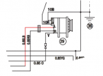
According to the Yanmar manual, the tacho is fed from the W terminal on the alternator, so it would be an AC pulse.
 

VicS

Well-known member
Joined
13 Jul 2002
Messages
48,498
Visit site
The B type panel takes an unrectified signal from one of the stator coils

According to the wiring diagram in the owners manual it is the "Y" terminal but some of the diagrams in the service manual show it as "P"

1605880067503.png
 

GHA

Well-known member
Joined
26 Jun 2013
Messages
12,427
Location
Hopefully somewhere warm
Visit site
My idea at the moment is to read the pulse with something like an ESP 8266 and display a tachometer dial in html on a small display on the instrument pod.

Any help/ideas/criticisms gratefully accepted.

Welcome to the forum Rob!! ?

Can't help that much just yet but similar going on here.
Yet to test, this was designed with little knowledge but lots of googling , might work..
FIBSZnN.png

From a PCB made by jlcpcb based on an esp32, but with much more than just revs >
boatybits/boatymonpy

Wonder if sticking a drill on the alternator would work as a test to make it go round and round??

If you do go the microprocessor route than adding a few thermometers is dirt cheap and very useful, waterproof ds18b20 in ebay for less than the cost of a coffee.

If you have a nav computer running then signalk does a great job of, well everything, display on a webpage or save to a database.
 

pvb

Well-known member
Joined
16 May 2001
Messages
45,603
Location
UK East Coast
Visit site
Its labelled Y in the owners manual because its a yellow lead as richard .s shows

The wire may be labelled Y, but what is the terminal labelled? In the diagram I included, the wire is labelled O (for orange) and the alternator terminal is labelled W.

Do you have a link for the owner's manual you referred to?
 

VicS

Well-known member
Joined
13 Jul 2002
Messages
48,498
Visit site
The wire may be labelled Y, but what is the terminal labelled? In the diagram I included, the wire is labelled O (for orange) and the alternator terminal is labelled W.

Do you have a link for the owner's manual you referred to?
I think it has a yellow lead , which connects to the orange wire , rather than a terminal.

I have the manual downloaded. I think it came from Barrus' website but I cannot find the manuals download page now

here's the relevant bit snipped
1605885276506.png
 

pvb

Well-known member
Joined
16 May 2001
Messages
45,603
Location
UK East Coast
Visit site
I think it has a yellow lead , which connects to the orange wire , rather than a terminal.

I have the manual downloaded. I think it came from Barrus' website but I cannot find the manuals download page now

here's the relevant bit snipped
View attachment 103365

OK, that's an older manual from 2009, the one I looked at is a 2017 version (described as "6th edition"). I guess the OP can work out which he needs.

If anyone else wants the 2009 manual, there's a download here - https://j109.org/docs/yanmar_ym_series_operations_manual_v2_21jan09.pdf
 

GHA

Well-known member
Joined
26 Jun 2013
Messages
12,427
Location
Hopefully somewhere warm
Visit site
My idea at the moment is to read the pulse with something like an ESP 8266 and display a tachometer dial in html on a small display on the instrument pod.

That circuit might actually work, just had a play with a variable buck power supply, the RPM pin sees 3.3v until pin 2 of the terminal t10 sees about 1v, then the 3.3v on RPM drops off to about 0.1v when the terminal gets up to around 3.5v - so an ESP with an interrupt set to detect falling might even work!!
 

RobHJ

New member
Joined
31 Aug 2012
Messages
4
Visit site
Thanks to everyone for all the info and feedback. At least no one has told me I'm mad to try this ;)
Now as soon as this lockdown ends I need to get back down to the coast and have a play.
Cheers
 
Top