270ah DIY LiFePO4 build

gregcope

Well-known member
Joined
21 Aug 2004
Messages
1,624
Visit site
The rebuild was a good chance to try out my Yaorea YR1035+ resistance tester to check the internal resistance of the cells. Measured through the busbars the resistances varied between 0.75 milli-ohms and 0.22 milli-ohms, but with the bus bars removed and measured direct on the terminals the resistances varied only between 0.17 and 0.16. That seems impressive to me to get such a well-matched set of cells as a grey import. The other lesson is that the busbar to terminal connection is clearly vulnerable to mismatch and, for anyone building a pack, that alone might justify the purchase of a resistance tester (which is ridiculously easy to use) to check that all connections are good. Cost of the unit from Ali Express is currently £42. It looks very well made. Real Four Wire Lithium Battery Internal Resistance Tester YR1035+ Nickel Hydrogen Lead Button Polymer Alkalinity|Battery Testers| - AliExpress

Off-Grid Garage has a video on it.


Mine all tested between 0.21 and 0.23 milli-ohms as measured on the terminals.
 

gregcope

Well-known member
Joined
21 Aug 2004
Messages
1,624
Visit site
I detailed here in my build post. It was interesting to see how variable some could be and a clean, sand, grease reassemble could improve them.
 

Poey50

Well-known member
Joined
26 Apr 2016
Messages
2,318
Location
Chichester
Visit site
One of the 4 cells on my 271 ah pack has been lagging behind the others so I thought I would put the 5 year warranty claim to the test. With barely any hassle a replacement cell arrived from RJ Energy in China last week. I top-balanced the pack with the replacement cell and did a fresh capacity test. The test was ended when any cell reached the low voltage cut-off figure of 2.9 volts. This came to a very satisfying 266.5 ah. So 4.5 ah has been lost from pack capacity in 29 months, equivalent to a respectable 0.7% loss of capacity per annum. Not bad for second-hand* cells bought on the grey market.


* These aluminium prismatic cells are invariably marketed as new and Grade A. That always needs to be taken with a large pinch of salt. The most likely account I have read is that these companies like RJ Energy are traders passing on ex-military cells, despite the websites showing factories and certificates. The cells do usually deliver the stated capacity but it is as well to check this with an inexpensive capacity tester - the green object on the right. Many of these 'firms' nevertheless have good reputations. The DIY Solar forum is a good source of information on respectable traders / 'companies'.

Now I have the ability to measure cell resistance as well as capacity I decided to check each individual cell (including the new replacement). Amazingly I found all the four original cells had identical internal resistance (0.16 milli-ohms) with capacities - measured at 20 amp discharge - varying only between 267 and 268 ah. They were remarkably well matched! Whereas the new cell had a 0.17 milli-ohm internal resistance but only delivered 213ah. All the problems of lagging of the old Cell 1 can't then be attributed to mismatch but instead must be due to either higher resistance in the busbar connections to that cell or to the 123Smart BMS which takes a small amount of additional power from Cells 1 and 4. I suspect the first of these is more significant and I have now used the same method as gregcope to get minimal resistance across all terminal to busbar connections, checked with the Yaorea tester.
 
Last edited:

vas

Well-known member
Joined
21 Jun 2011
Messages
8,085
Location
Volos-Athens
Visit site
sorry to revive the thread,

Quick Q, what rules have you set in your LifePO4 banks? do you let them charge at say 0.1C or 0.2C at 2 or 3Centigrade? or do you disable charging at these temps altogether and only use them for certain small loads until the weather improves?
Have 3-4C on board atm and expected to stay like that for the rest of the week, stock rules means that it's disconnected atm, wouldn't mind turn it on for some 1-2Ah loads (304Ah bank) and possible 2-3A charge via solar.

cheers

V.
 

Zing

Well-known member
Joined
7 Feb 2014
Messages
8,082
Visit site
I detailed here in my build post. It was interesting to see how variable some could be and a clean, sand, grease reassemble could improve them.
When I assembled mine I asked if I should grease the terminals and was told no by the manufacturer (CALB). I didn’t ask why, just did as I was told, so maybe there is a good reason to not do it.
 

Poey50

Well-known member
Joined
26 Apr 2016
Messages
2,318
Location
Chichester
Visit site
sorry to revive the thread,

Quick Q, what rules have you set in your LifePO4 banks? do you let them charge at say 0.1C or 0.2C at 2 or 3Centigrade? or do you disable charging at these temps altogether and only use them for certain small loads until the weather improves?
Have 3-4C on board atm and expected to stay like that for the rest of the week, stock rules means that it's disconnected atm, wouldn't mind turn it on for some 1-2Ah loads (304Ah bank) and possible 2-3A charge via solar.

cheers

V.

My BMS is set to disconnect the charge circuit at 5 degrees C and the load circuit at minus 10 degrees C. These are quite conservative figures but I don't live on the boat over winter so there is no downside for me. Your figures sound OK but does your cell manufacturer give a guide? I have a 1.2 amp heating mat under my cells which switches on at 2 degs C and off at 7 degs C. I'm not sure those figures are optimised for the mat as I haven't had cause to make use of that feature yet.
 
Last edited:

GHA

Well-known member
Joined
26 Jun 2013
Messages
12,517
Location
Hopefully somewhere warm
Visit site
just popped in to say hello, actually to share the joy!!!
Flying by the seat of my pants with no fuses which are on the way, no BMS yet but lots monitoring and fear. 😱
300aH Catl up and running. And with a 3Kw continuous inverter I can now weld away from shorepower!! 😎
About 230A from the batts for 2.5mm rods, less for 2mm. Massively useful for cruising anchors all the time.
These things are amazing, instantly all the constant niggling background stress of "Get the trojans back to 100%!!!!" disappeared.
So what are you guys setting 100% state of charge at? So far I´ve top balanced & charged up to 3.5V & called that full in the smartshunt. If it´s a bit out - who cares, loads headroom 😎
Playing around with some op amps to get mV accuracy of each cell recorded into the rapsberry pi, figures below are from smartshunt.
Multimeter on each cell on discharge has been identical or 1mV out between cells. Datasheet says 4,000 charge/disharge cycles down to 2.5v @ 0.5c. I´m so in love. 🤣🤣
400A t fuse coming, got 2 x 198A latching relays for the diy BMS. We´ll see how well the cell balance stays synced along the way.

e0b00zk.png
 

Poey50

Well-known member
Joined
26 Apr 2016
Messages
2,318
Location
Chichester
Visit site
just popped in to say hello, actually to share the joy!!!
Flying by the seat of my pants with no fuses which are on the way, no BMS yet but lots monitoring and fear. 😱
300aH Catl up and running. And with a 3Kw continuous inverter I can now weld away from shorepower!! 😎
About 230A from the batts for 2.5mm rods, less for 2mm. Massively useful for cruising anchors all the time.
These things are amazing, instantly all the constant niggling background stress of "Get the trojans back to 100%!!!!" disappeared.
So what are you guys setting 100% state of charge at? So far I´ve top balanced & charged up to 3.5V & called that full in the smartshunt. If it´s a bit out - who cares, loads headroom 😎
Playing around with some op amps to get mV accuracy of each cell recorded into the rapsberry pi, figures below are from smartshunt.
Multimeter on each cell on discharge has been identical or 1mV out between cells. Datasheet says 4,000 charge/disharge cycles down to 2.5v @ 0.5c. I´m so in love. 🤣🤣
400A t fuse coming, got 2 x 198A latching relays for the diy BMS. We´ll see how well the cell balance stays synced along the way.

e0b00zk.png

Excellent, I'm enjoying your enthusiasm! :)(y)

I top balance all in parallel once to 3.65volts then treat 3.5 volts per cell as full. What are you going to do for a BMS? Anxiety-fuelled monitoring won't last for ever - the excitement does wear off!
 
  • Like
Reactions: GHA

GHA

Well-known member
Joined
26 Jun 2013
Messages
12,517
Location
Hopefully somewhere warm
Visit site
Excellent, I'm enjoying your enthusiasm! :)(y)

I top balance all in parallel once to 3.65volts then treat 3.5 volts per cell as full. What are you going to do for a BMS? Anxiety-fuelled monitoring won't last for ever - the excitement does wear off!
Same top balancing, took days with an ebay buck converter. BMS diy but ready to get the wallet out if anything looks unreliable, already have 2 x self sustaining 198A relays which can be controlled with a micro controller, it will monitor cell voltage & temperature & prob current plus the smartshunt can send current data. The relays take no power once turned on or off, might parallel them for power out, chances of cell voltage getting all the way down are very slim but each step of the way will be do a bit them observe for a while to see what the real world is like. Very reassuring seeing cell voltages exactly the same to a mV.

Think I might live between around 20% soc to 80%. Rewiring some solar at the moment, just so cool watching what´s going on 😎

This cell voltage isn´t real, just total / 4 to get a handle on things, divide by 4 mental arithmetic slowly getting better 🤣

bfWNJAe.png
 

vas

Well-known member
Joined
21 Jun 2011
Messages
8,085
Location
Volos-Athens
Visit site
GHA, have a look at diyBMS if you want, not expensive, you order pcbs get s/w off Stuart and off you go.
Running it now for a year, works beautifully, has also CANBUS connection if you want to control victron mppt solar controllers (if you have them). Also has a v.accurate current monitor which is way more important with lifepo4 compared to la.
Open source of course, lots of development, worth a look.

have fun but as Poey says, you'll end up getting a bms for sure!
 

vas

Well-known member
Joined
21 Jun 2011
Messages
8,085
Location
Volos-Athens
Visit site
My BMS is set to disconnect the charge circuit at 5 degrees C and the load circuit at minus 10 degrees C. These are quite conservative figures but I don't live on the boat over winter so there is no downside for me. Your figures sound OK but does your cell manufacturer give a guide? I have a 1.2 amp heating mat under my cells which switches on at 2 degs C and off at 7 degs C. I'm not sure those figures are optimised for the mat as I haven't had cause to make use of that feature yet.
thanks, will probably get it going again as the backup Trojans now running are down to 11V (boat is 24V :eek: ) sun expected day after, was snowing all day today. Cannot find the literature that came with the batteries, will have another look!
@gregcope you remember any temp related info for the cells we have?

cheers

V.

PS. diybms doesn't do transistors, so you get full current flowing to whatever you wish, and sort out a high amp suitable for your needs to disconnect (I have a BlueSea 200A whatever thing) Don't think you can do the loads you want for arc welding and stuff via mosfets tbh
 
Last edited:

Kelpie

Well-known member
Joined
15 May 2005
Messages
7,767
Location
Afloat
Visit site
Don't let the best be enemy of good enough.
You could stick in a cheap Daly or JBD just to protect things whilst you figure out the long term plan.
 

GHA

Well-known member
Joined
26 Jun 2013
Messages
12,517
Location
Hopefully somewhere warm
Visit site
GHA, have a look at diyBMS if you want, not expensive, you order pcbs get s/w off Stuart and off you go.
Running it now for a year, works beautifully, has also CANBUS connection if you want to control victron mppt solar controllers (if you have them). Also has a v.accurate current monitor which is way more important with lifepo4 compared to la.
Open source of course, lots of development, worth a look.

have fun but as Poey says, you'll end up getting a bms for sure!
Not sure what benefit there would be from getting something off the shelf. Very accurate current is being measured & logged already as is state of charge, 200A relays are here and need no power to stay latched, need to sort accurate cell voltage measurement with differential op amps and a thermometer on each cell which is under way. Signalk can control the Victron smartsolar , might set that to switch off if/when batteries hit 80% soc. But first watch what happens and makes most sense in the real world. Not too bothered about active balancing unless the cells start to drift too much too quickly.
That feels better! Solar wiring tidied up and back on, just as the sun is going down 😎

Ku26hE9.png
 

vas

Well-known member
Joined
21 Jun 2011
Messages
8,085
Location
Volos-Athens
Visit site
fwiw, diyBMS is not off the shelf and I really like their celltop pcbs that do the basic measuring and passive balancing.
you got to keep track of all mA in and out in order to know SoC and that from a set point which you have to accurately (somehow) figure out.
in real life operation, I tail off current at 3.5V per cell (or really first cell that gets there - although there's some passive balancing at around 1A going on till the weak ones catch up)
Cells dont tend to drift a lot. Just make sure you dont run any pcl form say first or last cell as that will mess a bit the performance of that cell.
 

gregcope

Well-known member
Joined
21 Aug 2004
Messages
1,624
Visit site
thanks, will probably get it going again as the backup Trojans now running are down to 11V (boat is 24V :eek: ) sun expected day after, was snowing all day today. Cannot find the literature that came with the batteries, will have another look!
@gregcope you remember any temp related info for the cells we have?

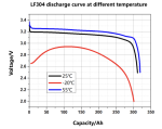
Charge to 0C, Discharge down to -30C according to the data sheet; No:LF304-72174

Screenshot 2023-02-08 at 20.26.12.pngScreenshot 2023-02-08 at 20.25.08.png
 
  • Like
Reactions: vas

gregcope

Well-known member
Joined
21 Aug 2004
Messages
1,624
Visit site
I run mine between 3.45 down to 3.2V, which is when my low batt alarm is. Can go lower and BMS cut off is 3V

Storage aim is 3.3V
 

GHA

Well-known member
Joined
26 Jun 2013
Messages
12,517
Location
Hopefully somewhere warm
Visit site
you got to keep track of all mA in and out in order to know SoC and that from a set point which you have to accurately (somehow) figure out.
Sorry, don't understand that.
Do you mean that current in and out of each cell needs to be measured down to mA resolution? Not come across that before.
A smartshunt is measuring amps in/out, 100% was set charging at 3.6v per cell when the current going in had tailed off to about 3A.

DiyBMS looks like it has microcontroller on each cell, can´t see the point of that with no active balancing. I´m going for op amps as differential amplifiers with unity gain, then an ADS1115 to do the measuring. Should be sub mV accuracy.

Something like ......
But will need to drop the + voltage a bit as op amps aren´t rail to rail. Maybe a low pass filter in case the inverter puts some noise in. Learning as we go along here 😊
An ESP32 to do the thinking, it can get current data from the smartshunt, control the latching relays & send voltage data o a raspberry pi.

Voltage followers soldered on a test PCB already, need to ad the differential op amps & test. JLCPCB will make the boards (plenty spares 😎) once it works.

JICiED7.png
 

vas

Well-known member
Joined
21 Jun 2011
Messages
8,085
Location
Volos-Athens
Visit site
I run mine between 3.45 down to 3.2V, which is when my low batt alarm is. Can go lower and BMS cut off is 3V

Storage aim is 3.3V
bit low on charging though Greg, I go up to 3.5V during season. Off season I typically get them down to 30-40% and disconnect them leaving the old Trojans to keep things up
 
Top