AngusMcDoon
Well-known member
A few weeks ago I posted a thread about the latest incarnation of an anchor watcher app and communications device. This app receives boat data from the instruments via my device over Bluetooth and compares their values against some pre-configured parameters and sounds an alarm if anything goes beyond the limits. Also included was an atmospheric pressure sensor. The data watched are depth (min and max), windspeed, pressure change, heading change, speed over ground and position change. The device has both NMEA2000 and NMEA0183 interfaces and is a user interface-less black box that redirects the data from the boat networks to my app via Bluetooth. The watching app itself is an Android app running on a phone or table. The thread is here...
Anchor watcher YappApp
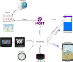
User sailoppopotamus suggested it would be better if it had an internet connection. Not being able to ignore a nerdy challenge like that, it now has. It still has the same features as before, so can still use Bluetooth when in range, but can now do anchor watching from sitting in the pub as well. Here's a diagram of what connects to what...

That's might be a bit confusing, so here's what's going on...
- Data are arriving via NMEA0183, NMEA2000 and the in-built barometer. Air pressure is sent out via via NMEA2000 so your instruments can pick it up.
- Data are sent out via Bluetooth. This allows, when in Bluetooth range, to get your boat data into either the anchor watcher Android app or OpenCPN running on an Android or Windows device. AIS data are also sent if available via Bluetooth so OpenCPN can use it.
- Data are also sent out via a GSM internet connection to a server on the internet (MQTT in the diagram). There are free servers available for this purpose.
- Data sent out via the internet can be received by the Android anchor watcher app when out of Bluetooth range, i.e. you've left the boat at anchor and gone to the pub.
- Data sent out via the internet can also be shown on a webpage I've created that so that anyone can see where you are and what your boat instrument readings are.
- The BlueBridge device has no user interface, so you configure it by sending it SMS text messages. You can also get it to send you the boat data that way by reply text message to one you send it, or it can send a Google maps location link.
For the internet connection a SIM card is needed in the device. Most of the PAYG ones expire monthly, but 1pMobile do 4 month ones for £10. That gives a GB of data which is enough for an update every 5 seconds over that period.
UKs cheapest PAYG mobile tariff
The device is up and running right now. You can see what's going on by going to this webpage...
http://miniwinwm.000webhostapp.com/
When asked for the code enter... 62C7959D
This number uniquely identifies the device sending the data, i.e. the one I have here (if anyone else had one, they'd each have their own unique code as it's derived from the IMEI of the device). It is saved as a cookie on your computer unless you reject that option in which case you have to enter it every time you load the webpage. The webpage gets the boat data directly from the MQTT server. There's nothing going on at the website server other than sending you the static webpage.
The data comes through every 30s so you may have to wait. There's a counter which shows the time since the last data reception. If you leave the page it will eventually lose the connection so click the Refresh button to reconnect. Clicking the Show boat button shows where the boat is and its heading. This map and boat position/heading are not updated automatically - you have to press the button each time you want to see the location or after changing the scale.
So what's new in the hardware design from last time? It's still using a Espressif ESP32 as that comes with Bluetooth built in. I've added a SIMCom SIM800L modem which can be bought on a small development board. This is only GPRS capable but that's fine for what's needed. GPRS will be discontinued eventually, so when that happens I'll have to swap to another modem. Modems often have strange power requirements, and this modem is no different in that respect. It needs 4.2 Volts and bursts of up to 2 Amps. That's a bit of a kerfuffle to create so I've added an off the shelf adjustable 2 Amp buck power supply.
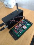
Here's the board layout...

And here's what it looks like when assembled...

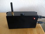
It's just a plain black box with 2 connectors, an aerial, an activity LED and an on/off switch...

The Android app is much the same with a few additions. You can now set up internet settings and choose between Bluetooth and internet. It also shows the time since data was last received, the reception period, and signal strength on the remote device...

Android app development and javascript in webpages are not my thang, so they are a bit clunky and could probably be improved. In the device the software is built on the previous project with the modem and data publishing added. It's a multi-threaded design using FreeRTOS. Modems are a complete gonad ache to program, especially in a multithreaded environment like this, and much of the extra effort was getting the modem to work reliably. It's not helped by their manuals being a 1000 pages thick, but I've left it running for a week and it didn't fall over (the device, not the manual).
This project is all open source, and also relies on other's open source works, particularly the ttlappalainen NMEA2000 library which I ported from Arduino to ESP-IDF...
GitHub - ttlappalainen/NMEA2000: NMEA2000 library for Arduino
My source and hardware design files are all here released under the MIT license (do what you want with it, but don't claim it's your work or try to prevent me from doing anything I want with it)...
BlueBridge project
While it's all working, there's still some work to complete (no manual yet for example) and some minor additions and bug fixes. There's also a 3rd spin of the PCB on its way as what you can't see on the pictures above are a couple of modifications underneath. I'll update this thread if there's anything new to report.
While the device is running as I type, as I'm still tinkering it will come and go, so if the webpage link above doesn't do anything, try again later. I'll generally try to keep it running in the near future.
If anyone wants to have a go at making their own one I'll provide assistance. I've got a few spare PCB's and all the other parts are available from RS or ebay.
Anchor watcher YappApp
User sailoppopotamus suggested it would be better if it had an internet connection. Not being able to ignore a nerdy challenge like that, it now has. It still has the same features as before, so can still use Bluetooth when in range, but can now do anchor watching from sitting in the pub as well. Here's a diagram of what connects to what...

That's might be a bit confusing, so here's what's going on...
- Data are arriving via NMEA0183, NMEA2000 and the in-built barometer. Air pressure is sent out via via NMEA2000 so your instruments can pick it up.
- Data are sent out via Bluetooth. This allows, when in Bluetooth range, to get your boat data into either the anchor watcher Android app or OpenCPN running on an Android or Windows device. AIS data are also sent if available via Bluetooth so OpenCPN can use it.
- Data are also sent out via a GSM internet connection to a server on the internet (MQTT in the diagram). There are free servers available for this purpose.
- Data sent out via the internet can be received by the Android anchor watcher app when out of Bluetooth range, i.e. you've left the boat at anchor and gone to the pub.
- Data sent out via the internet can also be shown on a webpage I've created that so that anyone can see where you are and what your boat instrument readings are.
- The BlueBridge device has no user interface, so you configure it by sending it SMS text messages. You can also get it to send you the boat data that way by reply text message to one you send it, or it can send a Google maps location link.
For the internet connection a SIM card is needed in the device. Most of the PAYG ones expire monthly, but 1pMobile do 4 month ones for £10. That gives a GB of data which is enough for an update every 5 seconds over that period.
UKs cheapest PAYG mobile tariff
The device is up and running right now. You can see what's going on by going to this webpage...
http://miniwinwm.000webhostapp.com/
When asked for the code enter... 62C7959D
This number uniquely identifies the device sending the data, i.e. the one I have here (if anyone else had one, they'd each have their own unique code as it's derived from the IMEI of the device). It is saved as a cookie on your computer unless you reject that option in which case you have to enter it every time you load the webpage. The webpage gets the boat data directly from the MQTT server. There's nothing going on at the website server other than sending you the static webpage.
The data comes through every 30s so you may have to wait. There's a counter which shows the time since the last data reception. If you leave the page it will eventually lose the connection so click the Refresh button to reconnect. Clicking the Show boat button shows where the boat is and its heading. This map and boat position/heading are not updated automatically - you have to press the button each time you want to see the location or after changing the scale.
So what's new in the hardware design from last time? It's still using a Espressif ESP32 as that comes with Bluetooth built in. I've added a SIMCom SIM800L modem which can be bought on a small development board. This is only GPRS capable but that's fine for what's needed. GPRS will be discontinued eventually, so when that happens I'll have to swap to another modem. Modems often have strange power requirements, and this modem is no different in that respect. It needs 4.2 Volts and bursts of up to 2 Amps. That's a bit of a kerfuffle to create so I've added an off the shelf adjustable 2 Amp buck power supply.
Here's the board layout...

And here's what it looks like when assembled...

It's just a plain black box with 2 connectors, an aerial, an activity LED and an on/off switch...

The Android app is much the same with a few additions. You can now set up internet settings and choose between Bluetooth and internet. It also shows the time since data was last received, the reception period, and signal strength on the remote device...

Android app development and javascript in webpages are not my thang, so they are a bit clunky and could probably be improved. In the device the software is built on the previous project with the modem and data publishing added. It's a multi-threaded design using FreeRTOS. Modems are a complete gonad ache to program, especially in a multithreaded environment like this, and much of the extra effort was getting the modem to work reliably. It's not helped by their manuals being a 1000 pages thick, but I've left it running for a week and it didn't fall over (the device, not the manual).
This project is all open source, and also relies on other's open source works, particularly the ttlappalainen NMEA2000 library which I ported from Arduino to ESP-IDF...
GitHub - ttlappalainen/NMEA2000: NMEA2000 library for Arduino
My source and hardware design files are all here released under the MIT license (do what you want with it, but don't claim it's your work or try to prevent me from doing anything I want with it)...
BlueBridge project
While it's all working, there's still some work to complete (no manual yet for example) and some minor additions and bug fixes. There's also a 3rd spin of the PCB on its way as what you can't see on the pictures above are a couple of modifications underneath. I'll update this thread if there's anything new to report.
While the device is running as I type, as I'm still tinkering it will come and go, so if the webpage link above doesn't do anything, try again later. I'll generally try to keep it running in the near future.
If anyone wants to have a go at making their own one I'll provide assistance. I've got a few spare PCB's and all the other parts are available from RS or ebay.
Last edited:
