Wet Exhaust Setup Help

DrGonzoMIA

Active Member
Joined
13 Jan 2022
Messages
53
Visit site
Hi all, hope everyone is well.

I bought a big ol' 40ft Steel Motor cruiser last year to live on. Built in 1979 as far as I'm aware and moved from the sea to canals. It has a ginormous Leyland 6/98 5.7l diesel engine.

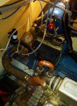
Haven't really been anywhere in it yet but want to make a start getting it a bit more refined. I appear to have a leak on the Vetus waterlock so got to googling exhaust systems and I'm not sure if my current setup is very good. Please see rough sketch I have attached which is not far off what it looks like currently. Biggest concern is water backing into the engine once off. I've had an idea of getting a 76mm stainless steel exhaust section from a car to create a goose neck after the waterlock. Would that be a good idea ?! Vetus sell a goose neck but it's a ridiculous price and out of stock everywhere.

Many thanks for any help or wisdom you can throw my way.
 
The principles of exhaust design are here vetus.com/en/exhaust-systems.html and as you can see your system breaks all the rules. You need a loop above the waterline between the waterlock and the outlet. It does not have to be a proper gooseneck, just a loop of proper rubber exhaust hose. The water and exhaust will be cool by the time it gets there. You also need an antisyphon valve in the saltwater circuit somewhere between the seawater pump outlet and the injection point into the exhaust.
 
Nice one thanks. I do have a small ant syphon loop just after the heat exchanger. I plan on getting a piece of 76mm stainless steel bent into a goose neck shape to sit just after the waterlock. Would that need to be vented ? Cheers.
 
It’s not clear where the water injection elbow is on the diagram.
Where is it ? Where does the hot gas and warm 84 degree ish seawater actually meet in your diagram ?

Metal pipage until the water is mixed , then rubber / plastic is ok .
65336451-3C0A-471A-AE75-89C93844C614.jpeg
B9EBA290-7F6C-4A29-9ADD-C47790C1EF60.jpeg
 
Definitely no vent. No need for stainless tube. Flexible hose is preferred.

Ok thankyou. I just find the 80mm outer diameter rubber hose difficult to bend in that kind of shape without creasing it !

Portofino, thankyou. I will try and upload some pictures but it doesn't seem to like doing it off my phone !
 
This is looking down into the engine bay. Hope its clear enough as had to re size and crop it alot to upload
 

Attachments

  • 20220113_190027.jpg
    20220113_190027.jpg
    793.5 KB · Views: 34
The principles of exhaust design are here vetus.com/en/exhaust-systems.html and as you can see your system breaks all the rules. You need a loop above the waterline between the waterlock and the outlet. It does not have to be a proper gooseneck, just a loop of proper rubber exhaust hose. The water and exhaust will be cool by the time it gets there. You also need an antisyphon valve in the saltwater circuit somewhere between the seawater pump outlet and the injection point into the exhaust.
Is it me or is the text underneath the two diagrams in the Vetus link above the wrong way round ?
 
Last edited:
Ok thankyou. I just find the 80mm outer diameter rubber hose difficult to bend in that kind of shape without creasing it !
If you're space limited or want a more compact arrangement you can get FRP bends from the likes of Halyard to create a gooseneck. I'd want to fit a gooseneck at the manifold, but that's just me.
 
Last edited:
Ok thankyou. I just find the 80mm outer diameter rubber hose difficult to bend in that kind of shape without creasing it !

Portofino, thankyou. I will try and upload some pictures but it doesn't seem to like doing it off my phone !
The latest exhaust hose is much easier to bend, but depends of course on your space limitations. As suggested Halyard Marine are the experts on this and you may well find a GRP U Bend and 2 lengths of hose will form a good gooseneck.
 
Top