VP AQ270 outdrive bellows and pipe

Refueler

Well-known member
Joined
13 Sep 2008
Messages
20,441
Location
Far away from hooray henrys
Visit site
I don't know if bellows are where water is getting into boat - but as I have no idea when last changed ... seller has no idea either ... I have asked local Yacht Hbr guys if they can change the drive bellows - exhaust bellows and cooling pipe.

I've watched videos and I am reasonably confident I could do it - but not so confident to be easy about it.

Yard guys say they haven't done that type before - but at least they should have the tools ...
No VP service / agents here ..

mmmmm decisions ........ I'm 70% get the yard do it ... I don't want a "Bouba" storyline !!
 

Refueler

Well-known member
Joined
13 Sep 2008
Messages
20,441
Location
Far away from hooray henrys
Visit site
I see that the exhaust and cooling pipe is not hard - but the drive bellows is not so simple.

I've watched a number of YT vids and I reckon I could do it - but would need to source the right tools. All the tools I have are metric and the VP is AF as I see .. and one spanner in particular needs modification due to lack of space round the bolt head.

I also need to have boat out of water ... my slip is not suitable at present - and trailer is not road legal ... means use of yacht hbr lifter.
 

madabouttheboat

Well-known member
Joined
20 Jan 2005
Messages
1,530
Location
UK, but for Covid it's England
Visit site
NO special tools needed to remove a 270 and replace bellows. Think they are all metric as well. Its been a while since I worked on a 270 but I don't remember having to source imperial tools to supplement my usual metric tool kit. There is one often overlooked place that can let water in on these and that is the gearshift cable hose. It goes through the transom shield below the waterline and is full of water when the boat is afloat. If its never been changed, which is quite likely, the hose may well be perished. I have had them literally fall apart in my hands before.
 

Refueler

Well-known member
Joined
13 Sep 2008
Messages
20,441
Location
Far away from hooray henrys
Visit site
According to various YouTube - one in particular is UK yard .. make big point about AF not metric ....

Anyway - not my issue now - boat is lifted and we have found the water leak ....

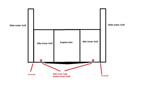
Once boat was in the cradles - the hull of course flexed a little instead of being fully water supported and water started to appear along a crack on stbd side underhull .. basically about where the longitudinal engine bulkhead is ...
Port side has signs of pending crack ...

Crack is about 20cms long ... video to upload shortly.

The boat originally had a 4cyl 130HP Volvo Penta - but 2yrs ago was swapped out for the 6cyl 170HP VP .... we wonder whether that may have stressed the hull and caused this ...

My GRP guy was there (interested to see the MoBo .. not for anything else) .. he looked and we reckon it will be a simple job ...

Drill to mark exact crack ends ... grind inside and out ... matt and resin to strengthen ... we will do both sides Port and Stbd.
 

oldgit

Well-known member
Joined
6 Nov 2001
Messages
28,265
Location
Medway
Visit site
Some early Bayliners had a reputation for longitudinal cracking in hulls.
Basically involved strengthening and repair.
 

scottie

Well-known member
Joined
14 Nov 2001
Messages
5,461
Location
scotland
Visit site
I seem to recall that the 4cyl engines might have been hanging on 2front mounts with the longer heavier 6 had rear mounts but my memory is definitely getting to wander (parkinsons)
 

Refueler

Well-known member
Joined
13 Sep 2008
Messages
20,441
Location
Far away from hooray henrys
Visit site
I seem to recall that the 4cyl engines might have been hanging on 2front mounts with the longer heavier 6 had rear mounts but my memory is definitely getting to wander (parkinsons)

The mounts are no problem ... the above video : at 4:05 and onward - you can see the GRP encapsulated transverse beam and mount looking down just to left of alternator. That with the outdrive bolted to transom.
 

scottie

Well-known member
Joined
14 Nov 2001
Messages
5,461
Location
scotland
Visit site
The mounts are no problem ... the above video : at 4:05 and onward - you can see the GRP encapsulated transverse beam and mount looking down just to left of alternator. That with the outdrive bolted to transom.
But if i am correct and bear in mind its a hazy source the mounts i am talking about are at the other end from the Alternator
But the 115 130 were often just hung on the stern shield as you said
 

Refueler

Well-known member
Joined
13 Sep 2008
Messages
20,441
Location
Far away from hooray henrys
Visit site
The 6cyl is definitely sitting on its original factory mount points ... I don't have a Volvo 164 car to hand to compare !! ;)

Was at boat again today ... my GRP guy is holding off a bit as there appears to be some water oozing from the GRP ... he may grind back into the crack more than we agreed just to be sure ...
 

scottie

Well-known member
Joined
14 Nov 2001
Messages
5,461
Location
scotland
Visit site
The 6cyl is definitely sitting on its original factory mount points ... I don't have a Volvo 164 car to hand to compare !! ;)

Was at boat again today ... my GRP guy is holding off a bit as there appears to be some water oozing from the GRP ... he may grind back into the crack more than we agreed just to be sure ...
It was only a comment but the car mounts will be different from marine but normally mounted in same area
The car mounts are not designed to absorb any thrust and may not even do anything other than kill the vibrations
Marine units support the weight and hold engine in place but you know this anyway
 

Refueler

Well-known member
Joined
13 Sep 2008
Messages
20,441
Location
Far away from hooray henrys
Visit site

Saga continues .....

Idea so far :

Having found that its basically car body resin with no fibres etc. We will sand this back enough so we can apply Osculati Marine Filler to sort the potholes - aeration holes etc. It looks like someone just troweled it on - then sanded before painting.

Once that is set - sand all back to smooth and then narrow longitudinal strip that covers crack and filler. Then a second wider longitudinal strip to spread any stress .. This will also be faired in so no sharp edges etc.

Internal work : Sand / grind back to good GRP ... then multiple matt layers to strengthen. We are considering running transverse GRP matt strips to build up 'grp beams' to further stiffen the structure. Initial thoughts were to add plywood bulkheads - but I decided not - as they can introduce sharp edge stress points and are less forgiving.
 
Last edited:

Refueler

Well-known member
Joined
13 Sep 2008
Messages
20,441
Location
Far away from hooray henrys
Visit site
It was only a comment but the car mounts will be different from marine but normally mounted in same area
The car mounts are not designed to absorb any thrust and may not even do anything other than kill the vibrations
Marine units support the weight and hold engine in place but you know this anyway

My comment about the car - was about the location of mounts ... not the mount system.
 

Refueler

Well-known member
Joined
13 Sep 2008
Messages
20,441
Location
Far away from hooray henrys
Visit site
Yard changed all 'rubber' on outdrive ...

Exhaust bellows - rubber was OK - but the metal spring spiral was broken in one place - risking puncturing the rubber.
Cooling water hose - generally ok - but had signs of chafe in one area.
Drive bellows - opening up the bellows showed it was near to splitting as many troughs had cracking of the rubber ... its possible that there may have been start of a split ..

At least I can now be confident that this is sorted for next few years !

Weather has turned wet and dismal - so hull repairs are delayed.
 
Top