fishermantwo
Active member
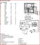
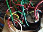
Have just replaced the timber for the instrument panel. While doing this I had to disconnect the wires from the back of the panel. Putting it back together was fairly simple because the leads are clearly marked or so I thought! One thick green wire with 30 marked on one end and switch on the other. The 30 is the pin 30 on the back of the starter switch. But where is the other end marked switch go to? The wiring diagram in the manual is not that helpful! Appreciate any help.