Underwater exhaust conversion...

vas

Well-known member
Joined
21 Jun 2011
Messages
8,077
Location
Volos-Athens
Visit site
hello all,

following work carried out on salon floor to improve sound insulation as discussed here:
http://www.ybw.com/forums/showthread.php?497788-sound-insulation-under-the-salon-carpet

and a general discussion on silencers:
http://www.ybw.com/forums/showthrea...-the-aft-deck-at-D-speeds-any-cheap-solutions

I think it's time to go ahead with something that will drastically lower the noise on aft deck at slow cruising (which is what I mostly do anyway...)

Bearing in mind I'm on 5inch (127mm if you wish) exhaust pipes costs for "dustbins" are much more than what I'm comfortable paying (Vetus is over 500 each side, Halyard and Centek are over a grand each side!) and unfortunately CoastalRides only has 4inch bins. I sketched some custom made ones to fit the available space. These turn out rather large (keeping volume in line with Vetus suggestions and the respective sizes of the others) taking a largish chunk of my e/r behind the gboxes and to the side of the hull. Further it's going to be a rather laborious process using a material that I really don't like, glassfibre.

Now, last week on the boatyard I had a look at an Azimuth 50something with CAT engines and underwater exhausts.
It's just a vertical pipe about an inch larger than the actual exhaust pipe going up half a metre and then reduced to the flexhose size for another 20odd cm. All that sits 1/3 from the side chine compared to mid of boat/keel area.

In my case that means half a metre of 6inch dia grp exhaust hose followed by a 45degree elbow of 5inch.
The contraption will fit in the frame behind the gbox leaving enough space to pull a gbox back 100 or more mm to disconnect and lift it off if need arises (touch wood not keen on doing it again on stbrd engine!). I'll clear the waterline by a safe 20cm just to be safe...
Then on the elbow I'll fabricate a 1.5inch (up to 2.0 that's to be discussed) take off that will lead to the normal existing outlet. The tell tale thing that relieves backpressure.
something like this ebay ad

I'll also get a corner made out of 12mm ply bolted and epoxied to the outside engine bearer and the frame aft of the gbox to secure/epoxy the pipe to and make sure it wont be knocked off somehow and flood the e/r (cannot imagine how but better be safe on that!). Mind doing all that means that the flexhose will only be a metre long on port and 1.3 on stbrd clearing up the path to the outside of the engines for servicing and general access.

Outlet will be vertical to the hull deadrise (or could be just vertical to sea level-not sure what's best) and offset to propshaft by 300mm (centre of the 6inch hole to shaft).

Enough of a description Q time:

A. any smart calc thing to establish if the bypass should be 1.5, 2.0 or more inch in dia?
B. what are the chances of this bypass being noisy and I end up adding a silencer to it as well :rolleyes:
C. prop aeration and all that, do they make any difference or no sense discussing them (7-9kn) or even at 19kn?
D. do I need to create a "spoiler" thing in the front side of the hole to hull joint in order to avoid backpressure on things exiting?

If I go ahead, I really only need:

An 90deg elbow that I'll cut in half to get my two 45deg:
https://www.ebay.co.uk/itm/Centek-M...ass-Elbow-5-x-90-Degrees-1200175/223181045324

and a length of six inch grp pipe like this:
https://www.ebay.co.uk/itm/Centek-F...32-Long-1641979-Marine-Vernatube/273673832640

I'll do the reduction mating and epoxying myself, it's a small enough job I can handle :D

my main problem other than a confirmation that this should work, is that I could only find the materials I need in the US, not keen on shipping a 3m pipe from there tbh :rolleyes: nor am I sure that the seller will be happy cutting in two (or three...) before shipping

Any comments/ideas gratefully accepted as always

cheers

V.
 

Andy Cox

Member
Joined
9 Oct 2018
Messages
166
Location
Falmouth, Cornwall
Visit site
Sorry vas, I can't help with your questions, but I'm following this with interest, as reducing aft deck noise levels at cruising speed - 8 - 10 knts - would be something I'd really like to do as well.

Andy
 

Portofino

Well-known member
Joined
10 Apr 2011
Messages
12,289
Location
Boat- Western Med
Visit site
Vas i will sort some pics out later when back from skiing today .
Amarti basically invented UW exhausts he did it first and as is the way eventually the rest caught up ( or not ? ) so let’s look at the maestros work :encouragement:
 

oldgit

Well-known member
Joined
6 Nov 2001
Messages
28,198
Location
Medway
Visit site
Installed a couple of waterlock type silencers in my last boat, reduction in noise levels was impressive and well worth the time and expence. Merely inserted unit(s) into existing flexible exhaust pipe and installing straps to hold it all down.
Over long distances the noise from straight through exhaust became very tiresome.The last straw was a 14 hour run back from Dunkirk to home.
Just how effective, rather than a constant rumble, you could actually hear the wash at back of boat.
 
Last edited:

vas

Well-known member
Joined
21 Jun 2011
Messages
8,077
Location
Volos-Athens
Visit site
Sorry vas, I can't help with your questions, but I'm following this with interest, as reducing aft deck noise levels at cruising speed - 8 - 10 knts - would be something I'd really like to do as well.

Andy

as soon as you accept two big holes at the bottom of your boat, you're half way there, not much in it tbh...

Vas i will sort some pics out later when back from skiing today .
Amarti basically invented UW exhausts he did it first and as is the way eventually the rest caught up ( or not ? ) so let’s look at the maestros work :encouragement:

thanks Porto (although there's of course invention but then there's also evolution :D )

a few pics from the e/r would help as well as relative sizes of exhaust pipe, vs by pass and final outlet at sea.
and an extra question I just remembered, you obviously antifoul this tube, does it get really infested with things? it must be rather dark, hot and miserable up there and hope that the various marine life don't like it.
I'll coppercoat it as the rest of the boat.

cheers

V.
 

MapisM

Well-known member
Joined
11 Mar 2002
Messages
20,479
Visit site
Vas, if I should give my suggestion to anyone who comes up with an idea like yours, it would be very simple: forget it.

First of all, a proper design of an u/w exhaust system is tricky even at build stage - in fact, I'm aware of boats built by very reputable yards, where the first hulls revealed major problems - to the point of wrecking engines and requiring radical modifications.
Secondly, you will struggle to find any half decent D boat whose exhaust aren't either dry stack or through transom with dustbin silencers. The simple reason is that no matter how well the idle bypass is designed (btw, that's another tricky component of u/w exhaust design), cruising at low speed with u/w exhausts is like having a plug on them.
Thirdly, well designed dustbin silencers are excellent for noise reduction - just hear how quiet a Sanlorenzo is, just as an example. And I suspect that for yourself, designing and having them fabricated in s/steel could be an option worth considering, also costwise.
Lastly, forget also what Portofino said. The reason why Amati perfected u/w exhausts (he didn't actually invent the system afaik, but I might be wrong, and that's irrelevant anyhow) has very little to see with noise reduction. The man was obsessed by boat efficiency, which is obviously more critical on fast boats, where engines are proportionally bigger in proportion to the hull size. So, his main goal was the maximization of the scavenging effect that only u/w exhaust can offer - the absolute best alternative, i.e. straight transom dry exhausts with no silencers at all, being in practice only applicable to racing boats. But on a boat like yours, exploiting the exhaust scavenging would be as effective as putting premium diesel in your tanks, if you see what I mean...

These are the reasons why I started this post saying that I would suggest to anyone to forget the idea.
But as we all know, Vas ain't "anyone", and I can't think of anyone else who might stand a chance to successfully retrofit u/w exhausts on a boat not designed for them...
So, if you should decide to go for it, I can't think of much more to tell you, aside from "good luck".
That would be yet another thread to follow with interest, that's for sure! :encouragement:
 

Portofino

Well-known member
Joined
10 Apr 2011
Messages
12,289
Location
Boat- Western Med
Visit site
Interesting subject that needs not to be dismissed.
But a lot to think about .
From the pics I think we can work out what’s happening.
Amarti was the first to use them . Primarily for a performance gain in terms of drag reduction by air rating the section of hull behind at P speeds .
They also work very well reducing exhaust noise at all speeds .Its this benefit why others copied to various degrees .I never said WHY he was the first btw MapisM , but there no reason Vas can’t grab a huge chunk of exhaust noise reduction by fitting them .
Reason I know this at D speeds in beam sea say 9 knots or whatever at say 900 rpm ( sub turbo spool - 1400 rpm ) if the boat rolls over exposing a UE orifice then we hear an almighty roar a deep bass roar verging on boom .
That noise even @ 900 is loud . Normally the exhaust are silent we hear nothing at D or P .
At faster speeds and P anything above 18 knots then the dynamic stability of the chines etc in the hull take over and the boat stiffens up so it does not expose the UE orifices .
Vas your boat is I believe stabilised so the roll exposure thing should not happen assuming you eventually get the software to work effectively?

Ours are not anywhere near the props , the gas is used to reduce drag .
Our ER is in the middle of the boat ( as all Amarti Itama , can’t speak for Ferretti variants with V drives ) This means the UE can be placed with a view to optimisation of any perceived or real performance benefits.

Without a diagram it’s not clear where you are thinking of placing yours relatively to the hull L .
I think as well as reducing drag distal to the orifice they reduce lift .
Not an issue at D speed , but how much spare lift have you got at P speed in the bank to throw away .?
You know my views on the fin position potentially compromising lift , well UE will be another step in that direction .
Not saying it won,t plane , just your increasing the bow high or stern sinking attitude at P speeds , more so in an unbalanced boat .
Amarti s boats have spades of lift due to the sharper V at the point of impact in the mid section so a bit can be exchanged for drag reduction.Also the centre of lift is directly under the mid sections where the engines and tanks are so they run flat with zero tab in a normal sea .
Think of see saw well balanced .
If a boat is not balanced like a see saw and lift is lost aft then it will tip back , hence the bow high attitude.I see loads of FB boats running looking like they are about to take off like a airplane, completely unbalance , nice mid cabins btw that clinched the sale .

A walk around a yard and you will see some with just a large hole for the UE only .No fart pipes at the transom .
A more detailed look and some have a little spoiler Fwds of the UE orifice .
Some are circular, some tear drop .They are all just under the chine so the gasses miss the stern gear .
Answering your Q - no we just antifoul inside and it stays clean it’s dark .

Ours has a sizeable pipe to the transom .
This is where I agree with MapisM re back pressure.
At tick over all the gas and water leaves the transom pipes .
1000 / 1200 rpm the same .
At the dock with the turbos spooling say over 1400 rpm then big bubbles exit the lateral aspects adjacent to the UE .So the straight through transom pipe is not big enough and gasses are forced out of the UE as the boat sits in the dock .


Ours are streamlined into the hull section ,there’s a deflector flap fwd and the rear edge is slanting , it’s like the gas is help out with suction .

So the various elements are
Gas pressure which is variable .Depends on the rpm
The boat speed - suction created above x knots
The transom pipe . Yes or no ?
WL position to the box internally
Size of the transom pipe relative to the main dia of the riser pipe .
Any hydrodynamic structures fwd or aft of the orifice .

Interestingly the majority or the water exits the transom pipe only a bit is diverted for cooling the internal exhaust.

There’s about a 20 cm air gap at anchor between the WL and the under of the box .

Pics ( it’s at the yard end of April so if you want more I can do some )

C8BF8A25-8DDF-4A1F-906C-1F8067E3DA4A.jpg
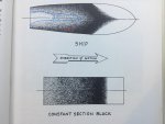
The deeper the V the darker the black V area or greater lift you have the play with .Ideally your engines want to be as close to the black dated V area.
The lighter dotted are suction pulling the stern down .Or if you drill a hole between the props any bilge water will be sucked out at P speeds .( obviously sink the boat at D speed )

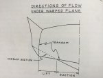
7209B389-B588-4313-ACAF-443554BB8EB4.jpg
X sectional suction / lift changes , So Vas how much lift have you got in the bank to forfeit ?

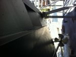
ABDFB883-D925-411D-94A8-A5A316AB3123.jpg
Just behind the distal stop - shows relative position to hull L

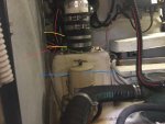
A72DD149-028B-4DF1-A48F-88A33B2AA285.jpg
Internal shot . blue the WL ( See strainer H ) .Red Gear box oil cooler raw water pipe to the top of the box .Yellow is the T off of the transom pipe with outbof shot main cooler seawater exit through the transom pipe not the UE .

B9E0D299-D61C-43DD-ADC5-288D81A43741.jpg
7B4AB193-464E-4F3B-B374-758D8E002ED4.jpg
Rectangle shape exit ( not just drilled a round hole ) Amarti is maxing out drag reduction of the edge of the box full width effect - also note the slanting rear surface and height differences between the fwd hull and rearwards section .

1B30145C-A942-4C5D-9E1D-B6B40995A434.jpg
Managing the seawater outs .The horizontal pipe is plastic and partially cooled at both ends .
All the outvwater is not just dumped it’s carefully fed in .Those two are one small from the main cooler and far one a gearbox out cooler pipe .The bulk of the main cooler out is the large black pipe which goes to the transom out .

DD47A542-0B1B-4314-AC8B-E3D5DE2E92D0.jpeg
RHS transom pipe - look at the water out .Most if not all of the gas at this speed 30 knots ++ will be sucked out of the UE .
You see trying to air rate those rear sections to reduce drag so he even seperate s the water from the engines .

FD4FA0EC-122D-447E-B606-A4A062FB0E6A.jpeg

Be careful with the waste water management.Not worried about full chat as the gas pressure with turbos spooling will blast everything down stream .But at tick over or sub turbo spooling you don’t want all that water pump water potentially running back when the boat rolls - over vessels wake etc . As in extreme rolls the relative height differences of the elbow and exhaust box may switch leading to water back flowing .

My transom pipes and UE for size comparison.
 
Last edited:

jfm

Well-known member
Joined
16 May 2001
Messages
23,834
Location
Jersey/Antibes
Visit site
Vas I agree with mapism. Just a few data points from mine, in answer to your Qs:

1. Yes there is a ramp to the leading edge of the u/w big exhaust holes. Like a bowthruster tunnel. And an indentation at the rear edge of the hole, so creating a suction effect.
2. The main exhausts are only just inside the chine, to keep away from water flow to props. Not 1/3rd in.
3. My bypass hoses are about 4 inch diameter and have their own silencers about 600mm long x 200 diameter. Main exhausts are about 10 inch per bank. So the bypass is about 1/12th the x section of the main.
4. Cat are a bit funny on this if the bypass exits the hull side just above w/line so I have secondary bypasses off the main bypasses. 50mm dia pipe going to a place under the swim platform that is perhaps 200mm higher than the main bypasses. This might be overkill.
5. As regards fouling/barnacles, all the bypass ducting is above w/line and gravity drains at rest including the main bypass silencers. The main exhausts are antifouled internally in micron 99 which works fine (as you know I hate coppercoat). You can reach inside, enough.
6. The dustbins contribute plenty to noise elimination, but so too does the underwaterness of thr main exhausts. In big beam seas when the stabilisers lift the side of the hull so high that the main u/w exhaust is revealed, you hear it. So I think you can get serious noise reduction if you get this project right.
7. I don't get any soot on the hull side from the main bypasses. I get a little under the swim platform from the secondary bypasses.
 
Last edited:

MapisM

Well-known member
Joined
11 Mar 2002
Messages
20,479
Visit site
Not sure I can face an Amarti (sic) write up but will brace myself.
The posts sequence is deceiving.
Considering the one minute difference, it's safe to say that this is a clear cut case of having seen it coming... :D
 

vas

Well-known member
Joined
21 Jun 2011
Messages
8,077
Location
Volos-Athens
Visit site
wow, lots of info and ideas thanks all.
bit too busy over the next couple of days then off to Brussels, will have enough time on the plane to work out my course of action.

wonder if there's some way of calculating gasses output by a motor in volume/sec or vol/min (in a way similar Q to Hurricane's how much air do engines eat...)
I'm asking as if at my typical 1200-1300rpm (off boost) 8kn engine exhaust output can be channelled to the bypass, I'm sorted for good:
Have a normal as described 6inch going to 5inch for the flexhose and a 2-2.5inch bypass with a much cheaper inline silencer.
Whenever I go planning, rest is sucked via the underwater thing... and I get yet another pressure sensor to issue backpressure warnings to know I'm fine

Thinking about it, iirc at that sort of revs each engine produces around 40hp (1.5-2lt/nm), maybe that's a starting point for the calcs or simply check what size is the exhaust pipe of a 40odd hp diesel engine, doubt it's more than 2.5in...

What may be a dealbreaker though is that underwater exist must be by the chine as it will mess my access to the outside of the engines. Only way out is if there's a serious slope say 45deg from vertical (er, or horizontal...) pointing outwards as well as another 30deg in plan towards aft to tidy up and keep the grp hose and rest of flex hose tidy and tight to the engine/gbox combo.
I'll post some sketches over the w/e

cheers

V.
 

novanta

Member
Joined
1 Nov 2007
Messages
109
Visit site
We did a exhaust conversion once on a Sunseeker Portofino 400. TAMD63 on shafts and Sunseeker homemade open exhausts, that was loud! At first we fitted inline Vetus exhausts due to price and delivery time but they were even worse... then we did the right thing and fitted two Halyard "dustbin" exhausts and they were worth every penny. There were expensive but now the boat was fun to use at non-planing speeds.
 

vas

Well-known member
Joined
21 Jun 2011
Messages
8,077
Location
Volos-Athens
Visit site
Have you seen these Vas?

https://www.vetus-shop.com/vetus-muffler-mv125-125mm-p-588.html

I was going to get a pair for the old boat which had no silencing....but then sold it :D

have you seen the price of them FARSCO then? :rolleyes:
further they are the wrong shape to fit in my e/r, bear with me!

Hi Vas

Check out Tony's info here re exhausts. https://www.sbmar.com/category/articles/exhaust-systems/

It includes a section on underwater exhausts. What he doesn't know about exhaust systems isn't worth knowing..

Steve
thanks Steve, I have this guy's work bookmarked and checking him out everytime I want to think about my exhaust. IIRC Latestarter pointed him to me. Excellent work.

We did a exhaust conversion once on a Sunseeker Portofino 400. TAMD63 on shafts and Sunseeker homemade open exhausts, that was loud! At first we fitted inline Vetus exhausts due to price and delivery time but they were even worse... then we did the right thing and fitted two Halyard "dustbin" exhausts and they were worth every penny. There were expensive but now the boat was fun to use at non-planing speeds.

Yep, all ppl that have done the dustbin conversion are happy, so looks like I'm going this way as well.


Now, sketched, measured, searched and that's what I have to report regarding dustbin TWO stage silencers (as in upright contraptions with inlet to outlet in different compartments separated with a horizontal baffle and a pipe connecting them) for my 5inch exhausts:

VETUS [site states: made of corrosion-free synthetic materials]:
MGP5455, 270mm dia, 450mm height, 23lt volume

MGS5455A, 400mm dia, 700mm height, 75lt volume

the next is their high performance one where it states that it's made of special blended composite NAVIDURIN(C)
HPW127, 380mm dia, circa 650mm height, 55lt volumen


CENTEK [state that it's made out of Class 1 Fire Retardant Epoxy Vinyl Ester Thermoset]:
1520500, 330mm dia, 483mm height, circa 40lt volume

and HALYARD [they don't mention what they are made off, but I guess GRP as they do a lot of things out of it]:
H001488, 445mm dia, 700mm height, 109lt volume

Now regarding sizing the silencer, I'd avoid the two extremes, 23 is silly so is 109 (no way to fit it in there!) so I'd move at around 70lt.
Placement is easy, box rests on two consecutive frames (400mm centres) stops at the outside engine bearer beam and goes 50-60mm heigher than the top of the side outlet. Construction in three pieces, bottom, top and a middle panel/baffle with a hole for the 127mm pipe joining the two compartments all bolted together at the flange with through bolts and nuts after adding some sika in between to avoid leaks.
Estimated volume is inxs 85lt! but I can easily reduce it a bit...

Theory is easy, practice I guess not so. Tried to built a petrol tank for my friend's custom 4.5m ply open boat, did a mould of the five sides (all sloping outside so easy to remove) applied liberal amounts of release agent, made it and eventually had to chisel out the mould :D - crappy selection of material for the mould, wasn't smooth, not enough release agent, etc.
Anyway, not too keen to using negatives, so thinking (and I'm going to check in the morning with the local epoxy dealer) of using a nomex honeycomb say 3mm thick (or two if it's sufficient) with a similar size cell to cut and shape each piece and apply a couple of layers of epoxy and mat to secure the shape. Test it on the spot and then take it back in the workshop to finish the extra layers. This way I should be able to built up to say 12-15mm the whole enclosure. Could also add inside a 3mm PVC foam for thickening and strengthening the lot.
A quick calculation says that each box will be circa 250euro in materials :eek:
ah, plus 300odd euro for the 127dia GRP pipe that I'll need over 2m of the thing to be ordered from Halyard as I've not found it anywhere else :(

artists impression of how the thing will look like:
muffler_dwg_1.gif


Now, although MM and JFM gave a few good reasons NOT to do u/w exhaust, I just tried sketching how the thing would look like.
JFM really? fart pipe of a fart pipe with silencers on each one!!! ffs mate cannot go any safer than that, can you? :D
Sketch has the 127mm pipe opening up to an 8inch one which slanted on both axis goes out just inside of the chine.
Definitely easier to built two pipes and I'd only do the connection :D
plus the mounting of the thing on the hull. Bypass would be a 2.5inch and I'd probably fit a normal silencer on it.
muffler_dwg_2.gif


ideas welcomed, tbh prefer the safety of an 80+lt box, but I also like the simplicity of the u/w

cheers

V.
 

5teve

Member
Joined
23 Feb 2016
Messages
262
Location
Western Australia
Visit site
Although I'm sure you are on to it..

I remember seeing a post re exhaust outlet and the height of your Iveco Risers - there wasnt much in it height wise. Just remember by putting the muffler in place you need to take into account the water height in the muffler so may be a good opportunity to make the system 'inherently safe' - again check out Tonys tips on an inherently safe exhaust system. New high risers with the water injecting on the downwards section and sufficient height so that flooding / backwash is just not possible means you will never have a turbo issue again. Ask how I know! mine has home made mufflers that with engine off and in the pen leave the water level a mere 50ish mm from the turbo outlet because someone cut the outlet pipe so it was a long way off the bottom of the muffler!- so a bit of wave action - turbos get wet - my solution short term until I can get risers made - was to add automatic drains on the mufflers - turn the engines off - solenoids open muffler drain to a shower sump and gets pumped out. Anyway as I said I'm sure you are on it but thought I would throw a reminder your way as the engine end gets forgotten about too often - even by builders..

Steve
 

5teve

Member
Joined
23 Feb 2016
Messages
262
Location
Western Australia
Visit site
Oh just noticed that you have the muffler split into 2 compartments?? ie dual stage

Why? just from the sound attenuation? or just the height? - the way you have it the top compartment is going to be full and almost flooding the input pipe - the output should be at the bottom of the top chamber. Could you not just do the traditional single chamber and run the output pipe up to height you need - makes for a simpler build - not that you are afraid of 'hard' or just by the centek ones and make a platform for them to sit on.. :)

Steve
 

vas

Well-known member
Joined
21 Jun 2011
Messages
8,077
Location
Volos-Athens
Visit site
Oh just noticed that you have the muffler split into 2 compartments?? ie dual stage

Why? just from the sound attenuation? or just the height? - the way you have it the top compartment is going to be full and almost flooding the input pipe - the output should be at the bottom of the top chamber. Could you not just do the traditional single chamber and run the output pipe up to height you need - makes for a simpler build - not that you are afraid of 'hard' or just by the centek ones and make a platform for them to sit on.. :)

Steve

Steve,

I expect sound absorbing to be much better on the dual compartment /stage ones, hence this approach.
Not sure that the output should be at the bottom of the top chamber tbh, except for one of the Vetus ones, all the others have the output either smack at the top or midway. Worse of all in this respect is the high performance one by Vetus where the outlet is on top of the top compartment...
I've not done all my studying yet, so cannot be of much more help atm!
OTOH, wouldn't mind reducing the width of the boxes and giving more height and getting the outlet midway of the top compartment.
Trying to sort out the construction of such a device and source 127mm OD GRP tube in Greece, that's fun!
I can only get the tube from Halyard in the UK via the Greek dealer but will be special order (see, over a month for a 3m pipe) so looking at alternatives.

Regarding the honeycomb I mentioned yesterday, doesn't work, so will be using a closed cell foam of 10mm and 60kg/m3 which means I can cut and shape each side of the box easily, then apply epoxy and mat on either side and sort of self support itself without having to make a mould, use release agents etc, v.happy about that, plus it's half the price of the honeycomb.

cheers

V.
 

vas

Well-known member
Joined
21 Jun 2011
Messages
8,077
Location
Volos-Athens
Visit site
Although I'm sure you are on to it..

I remember seeing a post re exhaust outlet and the height of your Iveco Risers - there wasnt much in it height wise. Just remember by putting the muffler in place you need to take into account the water height in the muffler so may be a good opportunity to make the system 'inherently safe' - again check out Tonys tips on an inherently safe exhaust system. New high risers with the water injecting on the downwards section and sufficient height so that flooding / backwash is just not possible means you will never have a turbo issue again. Ask how I know! mine has home made mufflers that with engine off and in the pen leave the water level a mere 50ish mm from the turbo outlet because someone cut the outlet pipe so it was a long way off the bottom of the muffler!- so a bit of wave action - turbos get wet - my solution short term until I can get risers made - was to add automatic drains on the mufflers - turn the engines off - solenoids open muffler drain to a shower sump and gets pumped out. Anyway as I said I'm sure you are on it but thought I would throw a reminder your way as the engine end gets forgotten about too often - even by builders..

Steve

Don't know what you've seen, but following the stuck turbo due to seawater backing into it, I currently have custom SS risers going up to almost touching the salon floor and then down for the mixer. A good distance above the hull side outlets, so no issues with seawater back flooding the lot either with the flex hoses now, or a silencer box, should be absolutely fine.

cheers

V.
 

vas

Well-known member
Joined
21 Jun 2011
Messages
8,077
Location
Volos-Athens
Visit site
back aching due to the removal of the port engine heat exchangers (this coolant one is a real b1tch and way too heavy, next time I should really spent two months in the gym first getting my body ready...) so stuck at home.
Did a 3D model of the muffler with a volume of around 85lt. Again two stage input on the lower part, pipe takes the gasses and seawater up and then out.
Dimensions should be fine, it's builtable easily with a 10mm 60kg/m3 density and I've sourced locally a 127mm OD 3.5mm wall grp tube for the ins, outs and in between pieces.

I'll probably order all the bits (well the grp tube that has a 2week lead time) and get on with it for the port side.

It's still rough around the edges, the flange between the top bottom and baffle is too crude and possibly too large, the red bits are the mixer of the elbow and the outlet on the hull side. Yes, I'll also have two 1/2inch outlets at the bottom of each compartment in order to empty the seawater in the bilge in case of having to remove it from there, wont be easy to handle with 30-40lt of water in it...
Comments appreciated as always:

muffler3D_1.gif


muffler3D_2.gif


muffler3D_3.gif


muffler3D_4.gif


muffler3D_5.gif


muffler3D_6.gif


cheers

V.
 
Top