tank pressure sensor any electronic engineers on here ?

Rgarside,

At last I picked all bugs out of my calculations and can send the attached description.

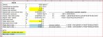
Of the spreadsheet I can only attach here a screenshot, not the working Excell file.

You can see all the steps. If you find any point you disagree with please notice me.


Cheers

Sandro
 

Attachments

  • PressureLevel.pdf
    PressureLevel.pdf
    208.2 KB · Views: 5
  • press.Lev.Spreadsheet.JPG
    press.Lev.Spreadsheet.JPG
    112.6 KB · Views: 5
Very good - I wrote out the identity based on the pressure at the bottom of the impulse tube, so the resulting equation was a bit different, but the results in terms of the values of "l" are identical.

I can see how you calculated what you refer to as the "measured head" and the "error". But we know that the measured pressure divided by rho*g is not equal to the head of liquid in the tank, so why treat it as if it is and then talk about an error? Hence I gave my results as the measured pressure corresponding to the actual tank level.

On the meaning of the other root of the equation - the quadratic formula finds the two points where the parabola defined by the quadratic equation in question crosses the x-axis. It is possible that one root is beyond the bounds of the physical system, hence irrelevant - as it seems to be in this case. In other cases it can be relevant, there's some further discussion in Wikipedia if you search for 'Quadratic Formula' - this includes the case of complex roots to a quadratic equation.
 
Very well. By this time, whilst we were wearing our precious brain cells in this nice chat, The OP and Vas probably would have fitted the sensor on a tee at the bottom output tube, in the simplest of ways which is always the best on board.

All the best
Sandro
 
  • Haha
Reactions: vas
Very well. By this time, whilst we were wearing our precious brain cells in this nice chat, The OP and Vas probably would have fitted the sensor on a tee at the bottom output tube, in the simplest of ways which is always the best on board.

I'd have used a stick.
 
I'd have used a stick.
for what's worth, I do have a sight gauge on the side of the tank, so I already know how much diesel I have onboard and don't need a stick :p

but that's beyond the whole point, we are in a lockdown, bored, with time to spare, so lets get our brain-cells exercised and learn in the process!

cheers

V.
+1
Sandro
 
Hold it with the labelling print to the front, pins pointing downward and pin 1 is on the left.

Port 1 is the port pointing towards you when you have the device in this orientation and is the connection to your tank or the item you want to measure pressure in.
Port 2 is the reference side and in the case of measuring liquid level in an un pressurised tank it can be left un connected (at atmospheric pressure the same as your water tank).

For the analogue version:-
pin 1 - NC - not connected.
pin 2 - supply voltage
pin 3 - voltage signal out
pin 4 - ground or 0 volts.

This is not a device to measure 2 different presures and give 2 ouputs. It measures the difference between port 1 and port2 and gives an analogue output to show that diffential.

tnx, v helpful :)
 
k, anyone bored enough to take this thread further ?

i now have an signal of 2.0V with the tank empty and 4.5V with the tank full
this needs to trigger an analog VDO display that reads from empty to full = 0-180 ohms

how to convert this, i can build a circuit with instructions, but no idea where to start

would need to have some adjustment on the 'conversion' from V to R with a pot or use and arduino ?
 
What you need to do is find out what voltage on the meter to ground on the gauge changes the reading from zero to full.

You can then workout the scaling formula needed to convert the reading from pressure senor to that needed by the gauge.
 
or in theory go by the book and buy a digital potentiometer and hook it up with an arduino and get the same result with more money and hassle :D
note there are not many of them that are dip (so diyable, most are smd or whatever they are called), so go for Roger's suggestion above.

V.
 
What you need to do is find out what voltage on the meter to ground on the gauge changes the reading from zero to full.

You can then workout the scaling formula needed to convert the reading from pressure senor to that needed by the gauge.

can do the voltage measurement
but no idea how to do the next bit as it scale the voltage to resistance
or what to 'build'
 
can do the voltage measurement
but no idea how to do the next bit as it scale the voltage to resistance
or what to 'build'

You don't scale voltage to resistance you scale the voltage output from your pressure sensors to the voltage required but your level indicator for the equivalent sensor voltage.

The voltage output when the tank is empty is scaled to the voltage required by the indicator to indicate empty tank.

The voltage output when the tank is full is scaled to the voltage required by the indicator to indicate full tank.

You have the output voltages now get the voltages of the indicator then we can work it out.

It can be done with analogue op amps but it may be easier to use an arduino
 
tnx Roger

signal voltage with no water in the tank = 1.60V
tank full 3.80V

this is in the dashboard:
VDO Viewline Onyx Freshwater Gauge 12/24V - Use with VDO 10-180 Ohm Sender

link
(i don't have an 10-180 Ohm sender obviously and no access to the top of tank to fit one either)

can an analougue amp be designed build for this ?


Simon

The 10 to 180 Ohm refers to the variation or the resistance of the sender. The gauge reads a voltage that the sender sends to the gauge.

DSCF6114.jpg


This is a normal VDC resistance gauge wiring diagram

In this case the oil pressure sender resistance changes between 10 to 180 Ohms as the oil pressure changes same as your original fresh water level sender.

The gauge reacts to a voltage between the G connector and the negative of both the gauge and oil pressure sender

You I do have some VDO ocean gauges and will try to measure the voltage input to the gauge when the gauge reads E and then F.

As you have a different way of measuring the level of the freshwater your sender output is voltage and not resistance you need a piece of electronics the output voltage of your dender to the required VOLTAGE input to your gauge.

If the back of your gauge does not have the 3 terminals marked + , - and G you hav have a gauge that requires 4 to 20mA.

This is the way both my 2 fresh water and 3 fuel senders work and I have 2 VDO 4 to 20 mA gauges.

My oil pressure and water temperature gauges are resistance senders but for duel gauges.
 
  • Like
Reactions: vas
checking out the internet, one can use an LED / photoresistor ?
the LED brightness is proportional to the voltage of the sensor
and the photorestoris is proportional to the required resistance

am i making any sense ?
noo idea how to set a circuit like that up ......


OK do you have a multi meter that can read DC volts.

If so you will need a variable resistor/ potentiometer about 500 to 1000 ohms.

You connect the ends of the pot to + and - on the gauge and the + to 12Vdc and the - to negative of the 12VDC supply.

The wiper / center pot connector goes to the G on the gauge.

In adjusting the pot the gauge should move from E to F or from F to E.

You can then measure the voltage between the - and G terminals on the gauge and note the voltage when the gauge reds E and also when it reads F.

This can then be used to map the voltages on the output voltage of the sender with the inputs voltage of the gauge.

Hope tins makes sense.
 
Top