Split charge / Isolator and solenoid relay bypass failure.

SPWiddy

New member
Joined
16 Mar 2017
Messages
14
Visit site
My starter battery was depleted at anchor even though the isolator switch had been turned to the off position.

I found that the inverter was drawing from the starter battery even when the iscolator switch was turned off.

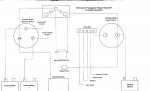
Installed is a Sure Power 1202 diode split charge device with a solenoid relay which when energised by the engine start circuit bypasses the diode to allow the alternator to charge the house bank.

When I tested the diode with my multi meter, it showed the diode to be closed circuit and passing voltage both ways so shows as failed, also when the solenoid is energised it is testing as open circuit and not passing voltage when energised or de-energised although it make a healthy click when powered up.

As both seem to have failed my questions are these,

1, Could the failed solenoid ( assuming it failed first) have caused the diode to fail by holding back the alternator current for extended periods whilst motoring?

2, Should I replace the failed components like for like, or are there better products available now?

3, Am I missing something?

Steve.

Ps Boat is a Hunter Passage 42.
 

PaulRainbow

Well-known member
Joined
16 May 2016
Messages
16,011
Location
Suffolk
Visit site
Steve, this sounds like an odd arrangement, why the need for a diode and a VSR ? There are three connections to the diode, one to each battery bank and one which normally goes to the alternator, where is this connected ?
 

pvb

Well-known member
Joined
16 May 2001
Messages
45,604
Location
UK East Coast
Visit site
2, Should I replace the failed components like for like, or are there better products available now?

No, don't replace these, as PaulRainbow says this is an odd arrangement and there's no need for a relay.

You could instead use a VSR. Or you could use a low-loss splitter (eg Quick ECS162 or Sterling equivalent).
 

neilf39

Active member
Joined
6 Apr 2005
Messages
972
Location
Milton Keynes, Bucks, UK
www.konsortkoto.wordpress.com
So you have a bypass for your split charge device? Why? Seems to defeat the object of having it as it should be charging both batteries. Only thing I can think of is if the surepower goes via the isolator switch which if off and you can hand start your engine then it would stop the alternator blowing up as there would be a battery connected.

How is your inverter actually wired in? It sounds like it does not go via the isolator switch so either is wired direct to the house or starter battery. An inverter, unless it is switched off at the unit, will take a current even if it is not powering anything so unless it is isolated from the batteries will eventually flatten them.

If the inverter is not isolated by the isolator switch and drawing current from the starter battery then only way I can see this happening is if the inverter is wired to the start battery or the surepower has failed giving a path between the house and starter battery, especially if you say the strange bypass circuit stays open.

If you disconnect one side at the surepower unit to break the possible path and the inverter stops drawing then sounds like the surepower is broken.
 

PaulRainbow

Well-known member
Joined
16 May 2016
Messages
16,011
Location
Suffolk
Visit site
If the diode has failed in such a way as to be allowing current to flow in both directions then the batteries are in parallel and no matter whether the engine battery isolator is on or off any loads imposed upon the domestic bank will be shared by the engine battery. The inverter, how ever it is connected, can therefore drain all of the batteries.
 

PaulRainbow

Well-known member
Joined
16 May 2016
Messages
16,011
Location
Suffolk
Visit site
Steve, what is the battery switching setup ? 1-2-both, separate switches etc ?

Where are the connections for the relay and diode made ?
 

SPWiddy

New member
Joined
16 Mar 2017
Messages
14
Visit site
Thanks for the replies,

I have a diagram which would explain the situation, but I cannot upload, it wont let me, maybe a permission problem, just need to upload it from my desktop.
 

PaulRainbow

Well-known member
Joined
16 May 2016
Messages
16,011
Location
Suffolk
Visit site
Thanks for the replies,

I have a diagram which would explain the situation, but I cannot upload, it wont let me, maybe a permission problem, just need to upload it from my desktop.

I'll PM you my email address Steve, send it there and 'll take a look and post it here.
.
 

PaulRainbow

Well-known member
Joined
16 May 2016
Messages
16,011
Location
Suffolk
Visit site
I consider you to be one of the "experts" so what do you think?

I don't think the OP wants to change the current system too much, so it's a case of fixing what's gone wrong and hopefully making it a little more fail safe.

The diode pack is a simple split charge diode, the sort used for charging two battery banks from a single charge source. As it's only been using one of the diodes the other one should be OK, so Steve should be able to swap the cable over to that diode.

I don't like the relay. If it fails open circuit it gives the problem that Steve has now, resulting in a flat engine battery and a blown diode. If it fails closed circuit there is a different fault, but with the same flat battery. I would replace the relay with a low loss splitter, such as the ones PVB suggests, or the Victron one. One designed for charging three banks will mean that all of his batteries will get charged from the alternator, irrespective of what has been selected with the 1-2-both switch. In the unlikely event that it fails it won't destroy the diode.

That gets the system back up and running and makes it a little more fail safe without making big changes or spending big money.
 

dk

Well-known member
Joined
30 May 2001
Messages
1,406
Location
N Devon
Visit site
That all looks wrong to me. Not sure the diode splitter is even doing anything as it is wired. The B+ from the alternator should be on the central terminal of the splitter and the switch wire common (feed?) to the house bank should be on the other side of one splitter diode, the starter battery pos on the other. As it is, with the solenoid 'closed' it simply shorts the diode, so achieves nothing.
Needs rethinking completely.
 

PaulRainbow

Well-known member
Joined
16 May 2016
Messages
16,011
Location
Suffolk
Visit site
That all looks wrong to me. Not sure the diode splitter is even doing anything as it is wired. The B+ from the alternator should be on the central terminal of the splitter and the switch wire common (feed?) to the house bank should be on the other side of one splitter diode, the starter battery pos on the other. As it is, with the solenoid 'closed' it simply shorts the diode, so achieves nothing.
Needs rethinking completely.

So does your assessment. Care to try again ? :)
 

Forty_Two

Well-known member
Joined
23 Sep 2002
Messages
1,104
Location
La Napoule/Oxfordshire
Visit site
The diode is to stop the starter battery discharging into the house system when both switches are on & the engine is not running. Very sensible & means both batteries can be left switched on at anchor.

The relay bypasses it to maximise charge from the engine alternator.

As suggested the other arm of the diode unit is probably ok.

Could you have inadvertently pressed the starter whilst the starter battery was switched off?

If so that could have blown the diode & then welded the relay contacts together when it operated.
 
Top