Rebuilding a 1968 Sabb model GG

Eventually got the gear housing together today. All looking good, the cam shaft turns freely and runs true. It was a bit of a pig, as I was driving the shaft into the small bearing whilst lining up the outer bearing with the housing the eccentric pulley accidentally rotated by a few degrees which in turn bottomed out the cam shaft key. I couldn't understand why it would go in the last 5mm. When I worked it out it was a little late and I had put a burr on the pulley which stopped the eccentric ring rotating freely. So out it all came, some delicate filing and reassembled without too many more issues.

Tomorrow I should be able to fit the hand start sprocket and the front gear cone.

Question: luckily my manual has additional updated notes from Sabb South before they went out of business and within them it states that Sabb controlled swell gaskets don't require any cement just a smear of grease what does the panel think?

Kieran
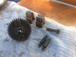
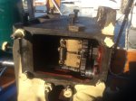
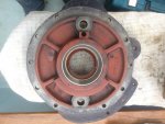
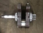
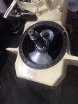
A dab of grease is fine, actually a smear is the better description. Am well impressed, especially the DTI! Just a thought, write it up, label the pics and send it off to David Pugh, PBO editor, it looks like the makings of a damn fine article!
Stu
 
Thanks for the encouragement. It really helps being able to ask questions here, I am a practical person but other folks' experience gives the confidence that you are doing things the right way and that helps to eliminate expensive mistakes. Take it slowly with the correct method and correct tools seems to be half the battle.

Cheers

Kieran

Ps is there any point priming and painting the inside of the water jacket and outside of the cylinder liner?
 
Thanks for the encouragement. It really helps being able to ask questions here, I am a practical person but other folks' experience gives the confidence that you are doing things the right way and that helps to eliminate expensive mistakes. Take it slowly with the correct method and correct tools seems to be half the battle.
gg
Cheers

Kieran

Ps is there any point priming and painting the inside of the water jacket and outside of the cylinder liner?
I wouldnt, a chance of the paint coming off and blocking coolant channels?
The antifreeze should stop corrosion.
Stu
 
Stu, its raw water cooled. Yeah that's kind of what I was leaning to, I suppose the larger rust flakes just fall to the bottom of the jacket and slowly turn to dust. I was quite surprised at how clear the actual water passages were considering the 50 years of salt water corrosion. It's definitely better to keep it filled up with water especially now I'm here in the med and not much chance of freezing.


Kieran
 
The big end bolts are Verbus Tensilock self locking type, the manual says "the locking effect is reduced by repeated unscrewing". Do they need replacing?
I ordered new bolts from Sleeman Hawken but they sent the wrong type now they want £9 + vat each plus £45 UPS delivery or £17 international post that will take at least 2 weeks.
I am going to an engineer this morning to see if they can fabricate a new bush, if they can and I don't need new big end bolts I won't need to order anything from Sleeman.

Thanks

Kieran

Ps I can seize the bolts, they were before I removed them also is there a heat resistant locktite?
 

Attachments

  • IMG_0765.jpg
    IMG_0765.jpg
    94 KB · Views: 8
The use of the word "repeated" makes it sound as if you will be OK with using them again at least once ... but you would ideally need to know how many times those bolts have been used by previous owners.

If I were doing the job in the UK I would get new bolts to be on the safe side but that's clearly not going to be so easy for you.

I would probably use the old bolts if did not need to order anything else from the UK and torque them up slowly, then leave them for a day or two and re-check the torque to check that there has been no stretching.

There are high temperature versions of Loctite available - 266 will stand much higher temperatures than sump oil but only use a drop in case ever want to remove the bolts again .... but if you can seize the bolts with wire I wouldn't bother with the Loctite.

Richard
 
Thanks Richard.
Today I went to the industrial area where all the marine services are located in an attempt to have a new small end con rod bush machined. According to the people I have met, there is nobody in olbia who machines such items in bronze and I must go 100km to Sassari. I don't believe it for a moment but I decided it would be easier to order the big end bolts and small end bush from the uk. I will be able to put everything else together whilst I wait for the parts.

Kieran
 
Stu, its raw water cooled. Yeah that's kind of what I was leaning to, I suppose the larger rust flakes just fall to the bottom of the jacket and slowly turn to dust. I was quite surprised at how clear the actual water passages were considering the 50 years of salt water corrosion. It's definitely better to keep it filled up with water especially now I'm here in the med and not much chance of freezing.

Woops! brain not in gear!
Stu
Kieran
 
The gear housing is fully back together now. I have cleaned and fitted new bearings on the centrifugal governor and refitted. The injection pump has been fitted on its shims, I will have to check the fuel timing once the engine is back in the engine room or maybe when It is still in the saloon and being turned by hand (without starting it!) I have also cleaned up the governor door and it's associated parts and refitted.

Tomorrow I will prime and paint the new injector pipe and the old one to retain as a spare. I will fit the new races for the main taper bearings and overhaul the water pump with new valves and springs.

Question: is the fuel injection timing likely to need adjusting after a rebuild? I have comprehensive instructions of how to adjust it if needs be by adding or removing some of the shims.

Kieran
 

Attachments

  • IMG_0766.jpg
    IMG_0766.jpg
    95.1 KB · Views: 17
  • IMG_0767.jpg
    IMG_0767.jpg
    91.7 KB · Views: 14
  • IMG_0769.jpg
    IMG_0769.jpg
    94.9 KB · Views: 15
  • IMG_0770.jpg
    IMG_0770.jpg
    92.3 KB · Views: 15
  • IMG_0771.jpg
    IMG_0771.jpg
    90.1 KB · Views: 14
I love all these glib comments about how " tomorrow you will prime and paint" things. At the moment in Suffolk in my unheated workshop it is more like - today I will prime something and next week if maybe the primer has dried I will paint it!
You are doing a great job, I'm well impressed :encouragement:
 
Yes yes, very lucky to be out here, it's been lovely and sunny the past few days and really quite warm for several hours but cold at night, good for snuggling up with the woodburner. However there is a lot to be said for a workshop, albeit cold, for rebuilding an engine compared to doing it in the cockpit and/or saloon.

Kieran
 
I love all these glib comments about how " tomorrow you will prime and paint" things. At the moment in Suffolk in my unheated workshop it is more like - today I will prime something and next week if maybe the primer has dried I will paint it!
You are doing a great job, I'm well impressed :encouragement:

Why are you not working in the kitchen ? Isn't that what it's for ?
 
Injector pipe has been sprayed, I will add a few more coats of enamel paint over the next week. I have cleaned up the front bearing flange and fitted the new bearing race. Installed the new Timken tapered roller bearings onto the crank shaft. Somehow I seem to have lost the old main bearing shims, which has driven me mad today, so all I could do was test the crankshaft clearance with the one extra shim I had ordered. As expected it was not enough, I could hear the cage and rollers of the bearings jangling around. Luckily my last order from Sleeman Hawken is still in the uk so I quickly ordered some more shims ready to be shipped out next week.
Question: how do you measure the end play of the crankshaft and know how many shims are required? When I test fitted the shaft I could tell the bearings were not tight enough yet there was no discenable play. Is it a case of trial and error? Keep adding shims until the shaft feels stiff then remove one? The manual says I should have end play of 0.05 to 0.1mm, could I tap the shaft with a copper mallet from one end then put the dial indicator on and tap the shaft from the other end and take the reading?

Thanks

Kieran
 

Attachments

  • IMG_0778.jpg
    IMG_0778.jpg
    94.2 KB · Views: 11
  • IMG_0777.jpg
    IMG_0777.jpg
    96.6 KB · Views: 11
  • IMG_0775.jpg
    IMG_0775.jpg
    93.8 KB · Views: 11
  • IMG_0780.jpg
    IMG_0780.jpg
    89.8 KB · Views: 13
If you are trying to measure endfloat with the engine upright? I think that the weight of the crankshaft in the taper rollers could disguise the true reading. The shaft will tend to settle in some mid position.
Can you measure with the engine laid on its side?
 
Hi earlybird,
my manual states the following: "any wear of the rollers or race will allow axial movement of the crankshaft. If the movement exceeds 0.3mm the end play should be adjusted by means of shims under the front bearing race. The end play should be 0.05 to 0.1 mm. "
As far as I know axial movement is parallel to the axis of the bearing, i.e. In this case fore and aft, and I am presuming that the term end play is essentially talking about the same thing, how much the end of the crankshaft moves fore and aft. If my understanding is correct I am trying to find out what is good practice for measuring this? What you were describing sounds more like radial movement, please tell me if I've got this all wrong.

Many thanks

Kieran
 
No, I'm thinking endfloat, not radial. Trying to explain, perhaps a bit better. With the engine upright, due to the tapered shape of the bearings, the shaft will tend to settle under its own weight at the lowest point it can achieve, which won't be at either endways positions, but somewhere between the two extremes. This will make a clear-cut measurement of end-float difficult.
If the engine is on its side, on blocks, the crankshaft weight will be taken fully by the lower bearing. Pulling/pushing the crankshaft upwards by some means should, I would hope, give a much more clear-cut reading on the DTI. I'm assuming that your magnetic stand and DTI will be mounted on the upper face of the crank-case.
Just my thoughts, but I hope that's now a bit clearer.
 
Last edited:
Ahhh, I see what you are saying now. Many thanks that makes perfect sense. So what I could do is have the engine lying down on blocks, give the shaft a tap downwards then set the DTI, carefully remove the blocks and let the weight of the engine push on the shaft to show the movement. Or something on those lines.

Kieran

I agree that the engine needs to be lying down, but your method of measuring doesn't sound accurate enough. 0.1mm is 4 thousandths of an inch, you can't measure that accurately by moving the engine around. Can you not use feeler gauges ?
 
I agree that the engine needs to be lying down, but your method of measuring doesn't sound accurate enough. 0.1mm is 4 thousandths of an inch, you can't measure that accurately by moving the engine around. Can you not use feeler gauges ?

There might be a gap between a crank shaft nut or pulley and the crankcase into which a feeler gauge could be inserted ..... but it might be better to measure the thickness of the shims (unless its stamped on them) and then add or remove shims and torque up the end nuts until the point is reached where crankshaft turns freely but there is absolutely no chink sound when you move push the shaft to and fro. Then remove a 0.075mm or closest shim.

Richard
 
Top