Propshaft coupling advice

Hi. Thanks for the advice. I've been able to get a home-made screwdriver head on the screw but can't get enough pressure behind it. It pops out of the slot. I will remove the stuff attached to the engine and I've measured it all up and a socket will just about squeeze in there. It's the screw that bothers me. But I believe bristoljim might have given me the answer on that.
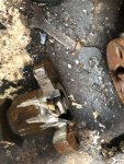
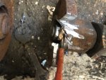
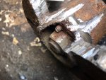
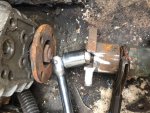
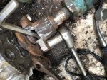
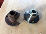
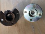
There is a way of loosening that screw. Get the sort of screwdriver bit that comes with an impact driver, and find one that is a good fit in the slot in the screw. Put it in place and pack Blu-Tack round it to stop it falling out. Re-assemble the coupling to the flange with the four bolts, trapping the screwdriver bit lightly so that it cannot come out of the slot, then carefully loosen it with a spanner.
 
what does the little ss screw go into, as it looks a bodge idea, and if the nut was loose would just turn round inside the coupling

have seen many screws that rest on the nut, but come in from 90 deg.

dissamble coupling for more room then scrape what that screw goes into, might be plastic from the look of it,, so a bit of heat on the screw, or give it a gentle clout side on. it cant be tough material as there isnt much strength in those ss screws.

then remove the big nut a few turns, heat the coupling, if afraid of overdoing it scrape some hand soap, on it. when it turns brown from conducted heat it is about 200 deg if i remember correctly, then if poss tension with a puller, and as others have said bang with 2 hammers at same time at right angles to the shaft, not along it.
 
I have a set of these to get into difficult screws

71Txz8JqvTL._AC_SL1500_.jpg


And a set like this

43984_ASDK-1.jpg
 
what does the little ss screw go into, as it looks a bodge idea, and if the nut was loose would just turn round inside the coupling

have seen many screws that rest on the nut, but come in from 90 deg.

dissamble coupling for more room then scrape what that screw goes into, might be plastic from the look of it,, so a bit of heat on the screw, or give it a gentle clout side on. it cant be tough material as there isnt much strength in those ss screws.

then remove the big nut a few turns, heat the coupling, if afraid of overdoing it scrape some hand soap, on it. when it turns brown from conducted heat it is about 200 deg if i remember correctly, then if poss tension with a puller, and as others have said bang with 2 hammers at same time at right angles to the shaft, not along it.
 
Well spotted (although it's as clear as day now that you mention it!). The R&D hasn't been in contact with the coupling has it? Thanks for the idea of the bobbin and split shaft coupling - I can't afford to shorten the length of the shaft so cutting the coupling off looks like a good option!
You say you cannot afford to shorten the shaft but I am sure if you look at the back end of your boat with the shaft back in its correct position you will have something like (at least)3" of shaft overhang which is far too much. You need no more than 1/2" to 3/4" between 'P' bracket or end of stern tube to the boss of the propeller giving extra shaft length to play with.. Another consideration is if you should need to purchase another prop shaft in the future it will be cheaper because you will need only one end machined. Jim
 
what does the little ss screw go into, as it looks a bodge idea, and if the nut was loose would just turn round inside the coupling

have seen many screws that rest on the nut, but come in from 90 deg.

dissamble coupling for more room then scrape what that screw goes into, might be plastic from the look of it,, so a bit of heat on the screw, or give it a gentle clout side on. it cant be tough material as there isnt much strength in those ss screws.

then remove the big nut a few turns, heat the coupling, if afraid of overdoing it scrape some hand soap, on it. when it turns brown from conducted heat it is about 200 deg if i remember correctly, then if poss tension with a puller, and as others have said bang with 2 hammers at same time at right angles to the shaft, not along it.
You say you cannot afford to shorten the shaft but I am sure if you look at the back end of your boat with the shaft back in its correct position you will have something like (at least)3" of shaft overhang which is far too much. You need no more than 1/2" to 3/4" between 'P' bracket or end of stern tube to the boss of the propeller giving extra shaft length to play with.. Another consideration is if you should need to purchase another prop shaft in the future it will be cheaper because you will need only one end machined. Jim
Before sliding the prop astern I only had about an inch of room anyway as you can see from the photo. Thanks again for your valuable input in this.
 

Attachments

  • Pbracket.jpg
    Pbracket.jpg
    201.5 KB · Views: 40
Success! Here's how I got there:

I had no luck whatsoever with getting the screw out.

1. Angle grinder. 'V' notch in the coupling flange all the way down to the 'retainer' which turned out to be brass.
2. Dremmell tool: cut the head off the screw and prized the brass bit out with a screwdriver.
3. Dremmell to the remaining threaded part of the screw/bolt.
4. Managed to get a socket on to the nut and a pair of mole grips on the coupling.
5. Used the flange on the gearbox to push an Allen Key against the end of the shaft. Used a grinder to create a notch in the coupling all the way down to the shaft.
6. The tapered shaft popped out!

Many thanks for all your suggestions and advice - very much appreciated.
 

Attachments

  • IMG_0844.jpg
    IMG_0844.jpg
    678.5 KB · Views: 66
  • IMG_0845.jpg
    IMG_0845.jpg
    679.1 KB · Views: 65
  • IMG_0846.jpg
    IMG_0846.jpg
    682.3 KB · Views: 64
  • IMG_0847.jpg
    IMG_0847.jpg
    997.6 KB · Views: 67
  • IMG_0848.jpg
    IMG_0848.jpg
    997.7 KB · Views: 68
  • IMG_0849.jpg
    IMG_0849.jpg
    285.8 KB · Views: 190
Last edited:
Looking at your last picture, where the taper meets the full diameter of the shaft, is that a line of dirt around the circumference, or is it corrosion? This could be a weakened area of your shaft. Suggest sterngear maker or specialist machinist has a look. Don't want to do all this work and refit a possible weakness.
 
Hi well done. where there is a will there is a way. With a little bit of Araldite and a lot of imagination you could use the coupling again. Again well done. Jim
 
Looking at your last picture, where the taper meets the full diameter of the shaft, is that a line of dirt around the circumference, or is it corrosion? This could be a weakened area of your shaft. Suggest sterngear maker or specialist machinist has a look. Don't want to do all this work and refit a possible weakness.
I've given it a good clean and it was muck with no signs of corrosion whatsoever!
 
Hi tis I again I have made some enquires on your behalf with Hamble props. Cost of machining taper and keyway £80>£100 or whole half coupling complete £180>£200. Hamble prop phone number is 01489574222. Dave's your man. Jim
 
Hi tis I again I have made some enquires on your behalf with Hamble props. Cost of machining taper and keyway £80>£100 or whole half coupling complete £180>£200. Hamble prop phone number is 01489574222. Dave's your man. Jim
Thanks again for your valuable help. I've asked a few local companies for quotes. It'll be interesting to see what they have to say. In the meantime I'm taking out the cutless bearing - which is another epic job!
 
Before you get drastic and start cutting things in half I have had this problem before. If there is room by far the easiest option is to remove the bolts on the engine mounts where they are attached to the bearers and move the engine forward. If you mark the positions before doing so and don't mess with the vertical adjustment sliding it all back afterwards should be easy and alignment not difficult to re-instate. Jam the prop to the ground with a suitable length of wood and get a long wrench on a socket to remove the nut. Put an extractor in the flange and if it wont budge use a blowlamp but shield the GRP from heat with something first.
 
Last edited:
Before you get drastic and start cutting things in half I have had this problem before. If there is room by far the easiest option is to remove the bolts on the engine mounts where they are attached to the bearers and move the engine forward. If you mark the positions before doing so and don't mess with the vertical adjustment sliding it all back afterwards should be easy and alignment not difficult to re-instate.
Hi. That's a very good idea but I have very limited room and can't move the engine back since the water intake filter is tight against the wooden bulkhead (aft to the filter) that separates the engine compartment from the under deck space that is home to the shaft, coupling and so on.

There's always a snag isn't there?! But there's a great saying in Welsh that I like: "Yn nhrofeydd y ffordd mae ei phrydferthwch" - that is, "The beauty of the road is in its twists and turns".

I'll get around this turn sooner or later!
 
HI. An update.

I asked Hamble Props for a quote but they never got back to me. I contacted Clements Engineering
http://www.clementsengineering.co.uk who produced this beauty for me for £160.

So problem solved. Thanks for all your advice/ideas etc.
 

Attachments

  • IMG_0976.jpg
    IMG_0976.jpg
    568.2 KB · Views: 33
  • IMG_0977.jpg
    IMG_0977.jpg
    485.9 KB · Views: 33
I am pleased you managed to get what you needed and at what I think a reasonable price, but I am very disappointed with the lack of response from Hamble props. The quality of there products is first class but would appear there PR is lacking the same quality. Jim
 
Top