NavMan fish finder wiring question

madabouttheboat

Well-Known Member
Joined
20 Jan 2005
Messages
1,575
Location
UK, but for Covid it's England
Visit site
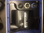
I have acquired a NavMan 4500 fish finder but it came with no power cable. I can source one but not being OEM I need to double check the pin wiring. I know from the manual that pin 1 is ground and pin 5 is positive on the socket with the black nut. What I don’t know is which pin is which on the back of the unit. Can anyone shed any light?
Cheers

index.php


478DB003-9B35-4651-80EB-DE0A4703AFFA.jpeg
 

Attachments

  • E051F439-70AC-40E4-9E62-2BFB8BE7EAEE.jpeg
    E051F439-70AC-40E4-9E62-2BFB8BE7EAEE.jpeg
    79.9 KB · Views: 88
Last edited:
The numbers are usually on the wire connection side of the connector (inside of the unit). It is worth checking with a bright light and magnifying glass in case they are also visible outside next to the pins. Otherwise you can open the unit to check.
If the connectors that you can source are really compatible then the numbering will be the same and you can safely connect to the appropriate pins.
Most recent electronics will have reverse polarity protection to accomodate idiot user errors so it is unlikely that you will do any harm with an incorrect connection especially if your 12V supply is correctly fused.
 
Thanks both. I will have a closer look today and see if numbers are visible. The lead I have has a red and black wire, as well as 6 others, but they test out to two pins that are next to each other (specifically the pins at 10 and 11 o’clock). I imagine that pins 1 and 5 would not be next to each other like this if they follow any sort of logic. I may be wrong, of course. Wouldn’t be the first time :rolleyes:
 
I was in exactly the same situation as you and used to know the answer but have long since forgotten. Here's my old thread: Plotter power leads (Navman Tracker)

In the end my son sorted it, he's away at the moment and the uint is on the boat.

Then...a few months later I was removing a bit of trimwork in the cockpit and both power and aerial lead fell out. Working!

Although the maps are well out of date it is a useful device.
 
Ok. Nothing on the outside so I took it apart and on the PCB there was just a ‘1’ next to one of the 8 connections. I then took a punt that like other examples I have found online, the PIN numbers were numbered clockwise (on the plug, anti clockwise on the socket) with 8 being the middle pin. This made no5 the pin at about 8oc on the plug or 4 oc on the socket. Stuck 12v to this pin, with the neg on the one labelled 1, and it fired into life. Happy days. Just gotta find a suitable transducer for it now.
 
Top