NASA BMI Battery Monitor Connections

mireland

Well-Known Member
Joined
26 Apr 2004
Messages
334
Location
Thames valley, UK
Visit site
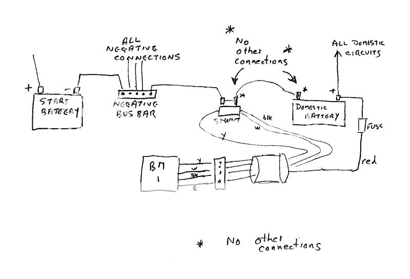
I have read previous threads on this and beetled off to the boat to check on my installation which always shows 0.1amp discharging. The battery negatives are all connected together, both domestic and start, then the start battery negative is connected to the BMI shunt. Is there somebody who can tell me if this is ok or should I only hav ethe domestic negatives going to the shunt and route the start negative to earth separately? Cheers.
 
If I understand your description properly it is very wrong.

All the negatives, for all the onboard equipment, including the engine, and the negative of the starter battery should be connected together by some means or another.

The negative of the domestic battery should be connceted to this common negative via the shunt.

There must be no connection to the domestic battery negative other than the shunt and there must be no connections to the battery end of the shunt other than the connections (black and white) to the BM1 itself

See below ( this does not however show the connection to the starter battery that enables modern versions of the BM1 to monitor the starter battery voltage)

scan0058.jpg
 
Last edited:
That's terrific Vic thank you - great diagram. You are quite right my starter negative goes to the point where you say NO OTHER CONNECTIONS and I will now move it. Can you say what effect this faulty installation will have been having?

I can't remember how it is on the boat but are the positive terminals of start and domestic joined or separate? Many thanks again.
 
You dont give enough info to say what your monitor is recording. It measures the current flowing through the shunt.

With separate domestic and starter batteries the positives would not normally be connected together ... they would not be separate if they were.
What is your charging system. Diode splitter, VSR, dual output gizzmo like a Sterling AB charger or do you have a manual system involving a 1, 2, both, off isolator switch.
 
I have something called a dual sense VSR cluster
Thats excellent. It means that you can connect a solar or wind or mains battery charger to which ever battery you want it to charge as the first priority then when that ones done it'll automatically go on to charge the other as well. You have the necessary isolator switches there and presumably some provision to link both batteries should the need arise.

The BMI is supposed to be for my domestic batteries.
which is why the shunt is in the negative connection to the domestic battery and all the current in or out of the battery flows through it.
 
Wow - so nice to have it explained properly! The VSR cluster has separate switches for each battery bank and an emergency switch to use the banks in parallel. Thanks for your help Vic.
 
Cheers PVB and Colvic. I have tried many times to set to zero but before long 0.1 appears again! When I have rewired a la Vic I will follow set up through again. I will have a new set of batteries too!
 
Does the BM1 monitor how much charge the alternator and/ or mains charger are delivering?

The BM-1 will monitor the combined charge/discharge flowing through its shunt into the battery or battery bank it has been wired to monitor, regardless of the source. This may not necessarily be the total output from an alternator/charger if it’s also charging another battery which isn’t monitored by the BM-1 (e.g. engine start battery).
 
Ok. ive been to the shops today and got myself said gadget.

Whats in the shunt? how does it work? it just looks like a piece of brass bar?

Years ago when we had old cars ALL the current went through your little round smiths ameter.

It looks to me that the current can bypass the shunt, obviously it doesnt, so how does measure amps in/out ?
 
... so how does measure amps in/out ?

The shunt is calibrated so that it has a standardised resistance (you may see a little area on it where it's been machined; this is to modify its resistance to a preset figure). When current flows through the shunt, a tiny voltage develops across it. The voltage is proportional to the current flowing, and the polarity of the voltage depends on which way the current's flowing. The voltage is read by a voltmeter which, as the shunt has a known standard resistance, can be calibrated in amps.

You don't need to know anything else, except that you must follow the installation instructions exactly.
 
You don't need to know anything else, except that you must follow the installation instructions exactly.

And an important aspect of the installation which is perhaps not made as clear as it might be is that there must be no connection to the domestic battery negative terminal other than the shunt and there must not be any otherconnections to the battery end of the shunt than the black and white wires to the monitor itself.

This diagram in post #2 of this thread shows this and it also shows how the starter battery negative is connected
(it does not I am afraid show the additional connection from the latest BM1s to the starter battery to enable it to give a voltage indication for the starter battery)
 
Thanks for that now i undertand. And rest assured i have followed the instructions exactly. Gto fire it up in the morning.
 
I have tried many times to set to zero but before long 0.1 appears again!

Mine does the same. To some extent it may be temperature dependant, but the bigger factor seems to be actual battery voltage. I have found best results are obtained when setting the zero when the battery has been sitting unused for a day or so. (the dead-band is about 8 presses, so you need to judge the centre of it). After several weeks with nothing connected the Ah reading is often obviously wrong (charge or discharge) and I routinely zero when getting on board.

Maybe my one is faulty and they are not all like this - who knows! Doesn't really bother me in actual use.

Vic
 
If I understand your description properly it is very wrong.

All the negatives, for all the onboard equipment, including the engine, and the negative of the starter battery should be connected together by some means or another.

The negative of the domestic battery should be connceted to this common negative via the shunt.

There must be no connection to the domestic battery negative other than the shunt and there must be no connections to the battery end of the shunt other than the connections (black and white) to the BM1 itself

See below ( this does not however show the connection to the starter battery that enables modern versions of the BM1 to monitor the starter battery voltage)

scan0058.jpg

Hi VicS. I am on a similar mission and found this thread the most likely to help but it seems your wiring diagram has gone. Do you still have a copy you can re-post please?

My set up is similar but the negative of the engine battery is connected directly to the negative of the service battery. I'm not sure if I can leave this in place and then just connect the negative on the service battery onward to the shunt. I only want to monitor charge across the service battery. Many thanks!

I dont know quite what has happened to the diagram in that post ( Very old thread anyway) but now hopefully attached to this post

NASA BM wiring (3).jpg

No you cannot leave the starter battery connected directly to the domestic battery .........( where it says no other connections it means no other connections). The exact consequences of doing so may depend upon exactly how everything else is wired but if you do you may find that the charging current for the domestic bank is not be recorded.
This diagram shows the use of a negative bus bar but there are a couple of other diagrams I posted on a more recent thread which give a slightly different option to the bus bar . See posts 18 and 28 in this thread http://www.ybw.com/forums/showthread.php?527869-Battery-Management One is of course basically NASA's own diagram.

I originally did the diaram because the instruction from NASA were rather poor and caused much confusion. They've improved them slightly now
 
Thank you so much - all diagrams help greatly so can now get this sorted. I've just bought the monitor (compact version) but the instructions did not have the Figure 2 diagram you had included in the other post. I'll probably go with the original bus bar solution. Thanks again. Nick.
 
Top