Making a new exhaust riser for MD2B.

Akestor

Well-Known Member
Joined
12 May 2018
Messages
428
Location
Athens, Greece
www.youtube.com
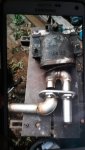
Old custom stainless steel elbow leaks from failed welding and the same does the small lifter. This is a project i d like to do for a long time and now it's the time. I decided to use plumbing fittings to make a new riser, as I found that some people have done this successfully. The riser goes up and then down where the water is injected in the bronze Y. I will also make a new lifter from vinyl-ester resin.
Nuts for locking the fittings at the desired position are available - not installed yet on the pics, it's just a test installation.
Any ideas for supporting the riser in place? Even the new flange from where the riser starts is heavy-duty, I guess a custom "arm" that will give the riser extra support may be needed.
Also, I am not sure whether it's best to attach the lifter on the engine so they all vibrate together ( riser and lifter), or install it on the hull and connect it with the riser with a flexible silicone hose for absorbing the vibration.
Have run out of inspiration so any ideas are welcome!
riser1.jpgriser2.jpgriser3.jpg
 
Just to comment that seems to be significant weight and leverage on a small flange, unfortunately the result of using threaded cast fittings. I would want it heavily bracketed to the engine block somehow so all. Over together
 
As a minimum you could rotate the pipe fittings to bring the C of G of the assembly as close to the engine block as possible. Even the first upright doesent need to be exactly vertical.
 
Just to comment that seems to be significant weight and leverage on a small flange, unfortunately the result of using threaded cast fittings. I would want it heavily bracketed to the engine block somehow so all. Over together
Agree, indeed there is the leverage factor, the actual weight of the fittings is around 4-5 kgrs which is probably multiplied by X at the edge where the Y fitting is.
 
Agree it's a lot of weight, but your second suggestion of a flexible connection to the engine is a non-starter IMO.
Is the H/E to which the riser is attached an aluminium casting? If so then the weight could well cause cracking.
 
Last edited:
Agree it's a lot of weight, but your second suggestion of a flexible connection to the engine is a non-starter IMO.
Weight is indeed a problem which i didn't thought when starting buying from different suppliers as nobody had all the fittings..Flexible hose will be after the water injection, at the bottom of the Y fitting and then to lifter which will sit somewhere below the Y.
 
Do you actually require the height ?
The after market SS elbow was rather horizontal slightly inclined downwards. The original volvo elbow does not rise either, but a riser ads safety to the system, making it impossible for the water to get in the engine.
The rising section might be omitted with a bigger water lift - muffler, decreasing the weight of pipe fittings overall. But if i could have both would be happier!
 
[QUOTE...Flexible hose will be after the water injection, at the bottom of the Y fitting and then to lifter which will sit somewhere below the Y.
[/QUOTE]
Am I missing something? The lifting section has to be before the water injection Y fitting. Earlier I was saying that flexible hose cannot be used to connect directly to the engine exhaust to isolate the lifter from engine vibration.
 
The weight is not acceptable then if the existing bend has been safe fort the life if this 50 years then unless you have changed the installation don’t reinvent the wheel

I am old enough to remember life before Volvo introduced their water injection elbow and familiar with your design
If you insist on use you elegant structure you will have to lag it to avoid heat transfer and as already said solve the weight problem
10 out of 10 for principal 2 out of 10 for practical application
 
Last edited:
[/QUOTE] Am I missing something? The lifting section has to be before the water injection Y fitting. Earlier I was saying that a flexible hose cannot be used to connect directly to the engine exhaust to isolate the lifter from engine vibration.
[/QUOTE]
The wet exhaust is also cast iron. The flexible hose will connect the Y fitting with the water lifter-locker which does not exist in the pictures but will be somewhere below the Y. The question is if it's better for the water lock to be attached to the engine ( so it moves along with the engine and riser, minimizing out-of-phase vibration between parts that could cause damage). Obviously, this is the best thing to do, but in absence of space for a bigger water locker, it might have to be installed away from the engine on supports next to the engine somewhere. That said, the whole riser will move along with the engine, but the water locker will not. Therefore, a soft silicone hose is needed, to absorb the vibration between Y and the water locker. Of course, these are just thoughts and not conclusions that's why i am asking for some ideas from the forum!
 
Am I missing something? The lifting section has to be before the water injection Y fitting. Earlier I was saying that a flexible hose cannot be used to connect directly to the engine exhaust to isolate the lifter from engine vibration.
[/QUOTE]
The wet exhaust is also cast iron. The flexible hose will connect the Y fitting with the water lifter-locker which does not exist in the pictures but will be somewhere below the Y. The question is if it's better for the water lock to be attached to the engine ( so it moves along with the engine and riser, minimizing out-of-phase vibration between parts that could cause damage). Obviously, this is the best thing to do, but in absence of space for a bigger water locker, it might have to be installed away from the engine on supports next to the engine somewhere. That said, the whole riser will move along with the engine, but the water locker will not. Therefore, a soft silicone hose is needed, to absorb the vibration between Y and the water locker. Of course, these are just thoughts and not conclusions that's why i am asking for some ideas from the forum!
[/QUOTE]
Have a look at the Venus catalog it’s all explained there
 
The weight is not acceptable then if the existing bend has been safe fort the life if this 50 years then unless you have changed the installation don’t reinvent the wheel

I am old enough to remember life before Volvo introduced their water injection elbow and familiar with your design
If you insist on use you elegant structure you will have to lag it to avoid heat transfer and as already said solve the weight problem
10 out of 10 for principal 2 out of 10 for practical application
Hi Scottie, are you referring to heat transfer from the dry part of the piping to surrounded air or back towards the wet exhaust?
I will assemble the parts again without the rising section ( simulating the volvo elbow ) to avoid extra weight and leverage and repost some pics
 
Hi Scottie, are you referring to heat transfer from the dry part of the piping to surrounded air or back towards the wet exhaust?
I will assemble the parts again without the rising section ( simulating the volvo elbow ) to avoid extra weight and leverage and repost some pics
The heat to air predominantly
 
I recently had to rebuild my high rise mixer. Mine is very heavy and it is bolted to the underside of the cockpit floor.
The right hand pipe is the dry exhaust inlet which is connected to the engine manifold by 1 metre of stainless corrugated pipe and lagged.
The unit and exhaust outlet is above the waterline so a syphon break on the seawater injection is not needed.
My engine is well below the waterline and a water silencer box cannot be placed below the manifold outlet so this system works well to stop the sea going the wrong way into the exhaust and filling the engine.
 

Attachments

  • 16057058244071719683300.jpg
    16057058244071719683300.jpg
    347.5 KB · Views: 46
Top