Oshbosh
New Member
great, thank you Downwest!
Great! Well done. The thermal cut out cables go behind the board probably (possibly) to one of the contacts or cables for the motor. If you can take the board and contactor out you should be able to get to it I would suspect that a suitable replacement would be available They are used in lots of applications and not specific to to one. I think that your connection block will be OK. Depends what you think on site.Good morning,
So, I have tried Alex's suggestion of connecting the button across terminals 1 & 4 and I can hear the contactors engaging, 24V measured coming out at the F1 terminal going to the motor! Amazing!
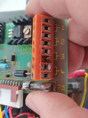
As was mentioned by Sam above, the terminal block has some scorch damage where the thermal cutout protection was connected so no way of knowing if this function is still operational, could be just bad terminals.
So, I think I can get the winch to work by connecting the button across terminals 1&4, however I would not be able to connect the thermal cutout protection as it is connected across terminals 3&4. Not sure what the implications of this are but I guess its needed. I will ask Lewmar.
So probably the terminal block should be replaced at the very least but think I still need to have the thermal cutout function tested, not sure how this can be done though.
I am in Venice at the moment but could send the unit to the UK for repair, thank you DownWest for your referral, I think I will try to find someone local first though as sending / receiving anything from the UK these days is a nightmare from here. I bought a gas strut recently from the UK for a hatch and it got held up in customs until I could provide a declaration from the manufacturer that it did not contain any Russian steel!
really thankful for all your help guys, I really appreciate it!
As you say photo to identify. With that control board it could be that they have used a thermistor or thermocouple, for example, to detect temp. Who knows?Find the thermal cutout and put a photo up here, it will be either a self resetting bi-metal cutout or a thermal fuse, both can be sourced separately
That may be a bit difficult to do Sam as it's likely mounted deep within the motor casing close by the windings unless its strapped to the side of the motor casing........very replaceable though...!Find the thermal cutout and put a photo up here, it will be either a self resetting bi-metal cutout or a thermal fuse, both can be sourced separately
Let's see what the OP comes up with. If you look at the picture in #8 there does not appear to be any thinner cables going to the motor. ( which is why I thought they may have used the cable temp.) It looks like input at the top and motor output at the bottom with two obvious thick cables and possibly another two connections at the rear but not identifiable. Perhaps OP can clarify?That may be a bit difficult to do Sam as it's likely mounted deep within the motor casing close by the windings unless its strapped to the side of the motor casing........very replaceable though...!
The motor will / should have 3 (or 2 if its only driven in one direction) 'thick' cables / terminals and then 2 thinner cables that appear the same as those of terminals 2 & 3 ( unless terminated and changed on route). Those are to the thermistor/ thermocouple in the motor I would think.
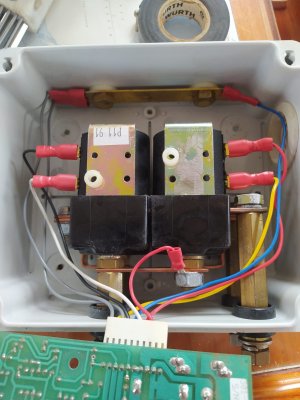
Yes quite possibly so Alex but I think that all the cables (larger csa) attached to PL1 are routed into the box via a conduit / gland on the top r/h side. At the top is the bat neg connection with a cable going off to the motor armature and at the bottom are 4 terminals with bat pos and a feed to the armature as well as a couple of feeds to the motor field coils either for direction control of speed adjustment ( depending on the mechanical make up of the winch and gearbox either could control the winching speed of the drum.) The small csa cables to pl2 will be + & - to the board as well as coil feeds fwd/ rev and some input into the current measuring system for overload control or if very sophisticated auto control to increase drum torque before it gets to an overload state again tied in with speed control etc. The last depending on how the motor is wound (series, shunt, comp' etc) may be a bit over ambitious with just the pcb and one ( albeit 'twin' ) contactor showing but who knows.....sounds like it all works just needs the thermal trip sorting.....if the new motor has one!Let's see what the OP comes up with. If you look at the picture in #8 there does not appear to be any thinner cables going to the motor. ( which is why I thought they may have used the cable temp.) It looks like input at the top and motor output at the bottom with two obvious thick cables and possibly another two connections at the rear but not identifiable. Perhaps OP can clarify?
I agree that the normal set up would be for the sensor to be in the motor area.
Yes thermal trip looks like it is faulty but the OP should bear in mind that it could be the control board that has the fault and not the sensorYes quite possibly so Alex but I think that all the cables (larger csa) attached to PL1 are routed into the box via a conduit / gland on the top r/h side. At the top is the bat neg connection with a cable going off to the motor armature and at the bottom are 4 terminals with bat pos and a feed to the armature as well as a couple of feeds to the motor field coils either for direction control of speed adjustment ( depending on the mechanical make up of the winch and gearbox either could control the winching speed of the drum.) The small csa cables to pl2 will be + & - to the board as well as coil feeds fwd/ rev and some input into the current measuring system for overload control or if very sophisticated auto control to increase drum torque before it gets to an overload state again tied in with speed control etc. The last depending on how the motor is wound (series, shunt, comp' etc) may be a bit over ambitious with just the pcb and one ( albeit 'twin' ) contactor showing but who knows.....sounds like it all works just needs the thermal trip sorting.....if the new motor has one!
 Perhaps a check with a multimeter across the thermal trip circuit to see if it is Open or Closed Circuit ( but what should it be in the first place.?? I would say normally closed.
To use without the thermal cut out you have to connect your switch to terminals 1 and 4 the thermal cut out is the original cables going to 3 & 4 . The original circuit is from terminal 2 out on 3 to thermal cut out and back in on 4.Hi, thanks for all the input, sorry for the lack of updates yesterday, it took me all day to install the new motor and gearbox, the access to the space was tiny, barely enough space to get my two hands in, anyway its done thankfully.
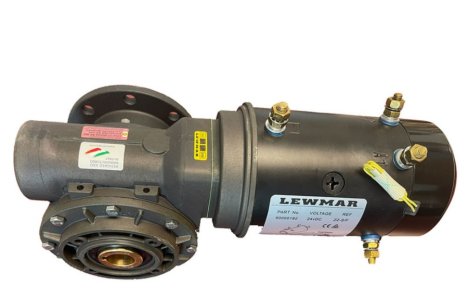
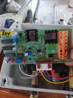
I have uploaded some photos of the motor and gearbox, the small luminous yellow cables are for the thermal cutoff and these connect to pins 6 & 8, counting from the top right on the PCB. You can see some burn damage to pin 6 and the brown cable which was connected there also had heat damage. I think this probably happened when the winch stopped working while driving it quite hard during docking. Even after this the contactors were still clicking away but the motor of course didn't work, after taking it all out everything was damaged beyond repair, hence the replacement.
A Lewmar expert told me in his opinion that the spindle connecting the motor to the gearbox was too short at that time and didn't extend all the way through the gearbox which may have contributed to the breakdown. The new spindle is much longer now and goes all the way through the gearbox.
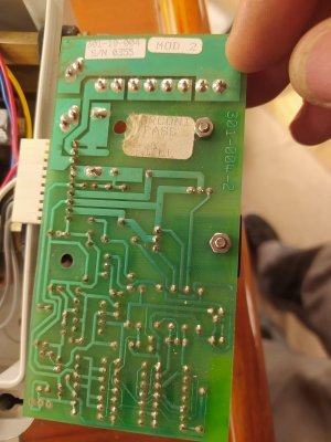
Also some photos of the board after separating from the rest of the gubbins below.
I cannot see anything which resembles a bi metal cut out or thermal fuse so I think the thermal sensing could be electronic in nature. The fuse on the board is fine.
I spoke to Lewmar yesterday and they advise that the winch will work if I connect across pins 1 & 8 but to be careful when driving the winch so as not to overload.
The top of the box shows the 8 pins as 4 pairs of terminals and says you connect the winch between terminal pairs 1 & 2 but I have tried all combinations of pins 1-3, 1-4, 2-3 and 2-4 and it doesn't work. Only pins 1 & 8 works ( Terminal pairs 1 & 4). Pins 2 and 7 for example, which are also part of Terminal pairs 1&4 does not work. Perhaps these pairs have to be connected together, the diagram on the top of the box seems to suggest so?
Ideally I would like to get it fixed properly, it could just require the terminal block being replaced but I'd like to know for sure that the thermal cutoff function is working. I think its interesting that it doesn't work when connected as normal across pins 1 & 3 and wonder if the thermal cutout has somehow disabled this when the winch was overloaded.
I will go to Mallorca tomorrow to do some training courses and bring the box to someone I hope can fix it, lets see!
Thanks for all your help, it is greatly appreciated!


") which is a tad confusing to say the least!
which is a tad confusing to say the least!Hi Alex......no winches of that size will have torque overload protection as well as winding thermal protection and as in a manual winch it will have the facility to change speed/ torque and so the overload 'protection' (which is current draw monitoring) will alter because the gearing has altered. The easiest way to achieve this is by changing direction of the centre shaft as in a manual winch. It's this I think which is what all the gubbins on the pcb is keeping an eye on.Yes thermal trip looks like it is faulty but the OP should bear in mind that it could be the control board that has the fault and not the sensor
As for all the conjecture about connections Having re-read the post I think the OP has a couple of winches not Windlasses! Puts a slightly different slant on things.
I'd get the soldering gun first before swapping it for another of unknown quality, as yours look v.good for the age and wonder why the guy in Palma has stock of old onesThanks Vas, I've tested the 8 terminal block pins on both sides of the board for continuity, each pair of pins is connected together (as per the diagram on the top of the box) so at the very least 1/2 -> 7/8 should operate the winch, but only 1 & 8 work. I'm sure you're right, the terminal block is buggered.
I might get lucky in Palma, the Lewmar expert who is helping me there said he may have some old control boxes for these 88s so as I'm heading there tomorrow I will hope that he can sort me out, otherwise time to get the soldering iron out!
Thanks!
It is worth noting that the heat damage to the terminal block has nothing to do with the motor load. It is purely down to there having been loose (bad) connections. The only load current through that block is the coil current for the contactor. Don't get it confused with motor load which goes through the contactor.I'd get the soldering gun first before swapping it for another of unknown quality, as yours look v.good for the age and wonder why the guy in Palma has stock of old ones
your call obvs, but would be easy to even pass over the 8 terminals with the soldering gun and new solder and testing again all terminals continuity...
Be easy to desolder the terminal block and replace it, for 97p 8-Way 3.81mm PCB Terminal Block Green 10A 150VI'd get the soldering gun first before swapping it for another of unknown quality, as yours look v.good for the age and wonder why the guy in Palma has stock of old ones
your call obvs, but would be easy to even pass over the 8 terminals with the soldering gun and new solder and testing again all terminals continuity...