Instruments can't see NMEA 0183 data from Ublox Neo-6M GPS module

lw395

Well-known member
Joined
16 May 2007
Messages
41,950
Visit site
The specs say 5V digital level but the GPS module outputs 2.9V, so presumably I should use the optocoupler to drive this converter as it's outputting 5V. There's going to be quite a daisy chain of bits and bobs, but they all use tiny amounts of power so as long as it works it doesn't matter.

The RS422 spec says that a 120-ohm resistor should be used to terminate the
receiving end of the line. What does that actually mean?
5V ttl logic high is usually anything above about 2V so often works fine with 3V3 cmos levels.
The termination resistor matches the line and prevents reflections or ringing on a long line. May be built into receiver IC. with shortish cables probably not needed anyway.
 

Elbows

Member
Joined
24 Dec 2016
Messages
137
Visit site
Here's the output direct from the Neo-6M module Tx pin. The signal is actually about 3.2V and it's much cleaner. The optocoupler seems to be distorting the waveform a lot.

Neo-6M Output.jpg
 

Elbows

Member
Joined
24 Dec 2016
Messages
137
Visit site
Using a line driver/transciever chip is a good call.
https://www.rapidonline.com/maxim-max485cpa-transceiver-rs485-rs422-82-0308
for example. Needs 5v supply but will be ok with 3v3 logic.
It makes it easier to flip the data + and - for one thing.

Yes, I think it's the next thing to try. Just ordered a module off eBay with that IC as suggested by RogerShaw. From what you're saying it sounds like it'll work fine connected directly to the GPS module which will avoid the distortion introduced by the optoisolator.

Unlike most things to do with boats, this stuff is so cheap that it doesn't cost much to experiment.

It really is a long time ago and what I got away with, with a particular bunch of instruments may not work with everything!

Understood, I'm not expecting guarantees, just grateful for any assistance. I'm way ahead of where I would have been if I was still struggling on my own.
 

ianj99

Active member
Joined
11 Nov 2009
Messages
2,103
Location
UK
Visit site
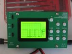
Just remembered that I got a cheap little LCD oscilloscope kit a few years ago. This is what it's showing between GND and the output of the optocoupler. X-axis is 0.5ms per div, Y-axis is 1V per div. It's updating at the same rate that the GPS is set to repeat (once per second) with virtually no jitter. Obviously this just the first part of the signal, zooming out means the peaks are so jumbled together that the low resolution display is just a mess of dots.

Seems to me that is what I should be expecting with the signal voltage being 0-5V and identical data being transmitted once per second.

View attachment 70351

I'm surprised its distorted, I've used them without problems . Have you got a resistor in the connection to the nmea input?
 

Elbows

Member
Joined
24 Dec 2016
Messages
137
Visit site
I'm surprised its distorted, I've used them without problems . Have you got a resistor in the connection to the nmea input?

Yes, 220R on both the data input and data output of the optosolator. Been thinking about it and I wonder whether it's because I used a longish wire which was draped around various power supplies and the like. I wanted to try it quickly and just grabbed what came to hand. When I tested the output directly from the GPS unit I had a very short connection. I'll try it again with a short wire.
 

Elbows

Member
Joined
24 Dec 2016
Messages
137
Visit site
Hi Elbows
Have you seen my recent thread on this? I don't understand any of this whatsoever but my friend who is helping me connect a similar GPS to VHF is pursuing Roger Shaw's line on the NMEA data, the RS422 thing. We are just waiting for the part from China.....
http://www.ybw.com/forums/showthread.php?497782-Using-a-DSC-radio-without-GPS-(DSC-newbie-warning!)

Just read it and it sounds like we have a very similar problem. Hopefully this will sort the electrical issues, but there's still the possibility of something not quite right in the software setup. I found a UK supplier of the converter module as I'm running out of time. It means paying 2 or 3 times the price but £2.70 won't break the bank.
 

Vladis

Member
Joined
20 Mar 2011
Messages
54
Visit site
Hello,

I did not read this thread completely neither I know the specification of your GPS module. However looking to the scope screenshot it can not work with nmea 0183 receivers. The output of the GPS has an idle state of HIGH and the Nmea183 receiver expects it to be low. So you will need an inverter.

However, if the input of your Nmea183 receiver device is opto isolated, you can connect Nmea+ to +5V and then connect TX from the GPS to Nmea-. This is the way to connect a Serial TTL device to a Nmea183 device.

Regards, Luis
 

ianj99

Active member
Joined
11 Nov 2009
Messages
2,103
Location
UK
Visit site
Hello,

I did not read this thread completely neither I know the specification of your GPS module. However looking to the scope screenshot it can not work with nmea 0183 receivers. The output of the GPS has an idle state of HIGH and the Nmea183 receiver expects it to be low. So you will need an inverter.

However, if the input of your Nmea183 receiver device is opto isolated, you can connect Nmea+ to +5V and then connect TX from the GPS to Nmea-. This is the way to connect a Serial TTL device to a Nmea183 device.

Regards, Luis

Yes, this is something I didn't notice in the scope traces.
So he need only rewire the opto isolator by connecting the 220r resistor between +5v and the collector and taking the output from this point. The emitter should be connected to ground instead of the nmea input.

This should work with both opto and non opto single ended inputs.
 

ianj99

Active member
Joined
11 Nov 2009
Messages
2,103
Location
UK
Visit site
Did you connect a ground return direct from AIS to Opto circuit?

Try rewiring the opto as in my previous post to invert the signal

Incidentally, the MAX232 inverts the signal so if it worked this would be why.
 

Elbows

Member
Joined
24 Dec 2016
Messages
137
Visit site
Hello,

I did not read this thread completely neither I know the specification of your GPS module. However looking to the scope screenshot it can not work with nmea 0183 receivers. The output of the GPS has an idle state of HIGH and the Nmea183 receiver expects it to be low. So you will need an inverter.

However, if the input of your Nmea183 receiver device is opto isolated, you can connect Nmea+ to +5V and then connect TX from the GPS to Nmea-. This is the way to connect a Serial TTL device to a Nmea183 device.

Regards, Luis

Well spotted, Vladis!

Actually GHA was on to it too but I missed his post for some reason. Apologies GHA.

Is rs232 same as ttl logic with idle high?

So he need only rewire the opto isolator by connecting the 220r resistor between +5v and the collector and taking the output from this point. The emitter should be connected to ground instead of the nmea input.

This should work with both opto and non opto single ended inputs.

OK, I'm probably just being thick but I'm having trouble seeing this. In my original setup the emitter wasn't connected to anything, and the cathode on the input side was connected to ground. My electronics knowledge is quite basic, so can you tell me exactly which pin connects to which wire. In order to keep things clear, I assume that input and output are in relation to the optoisolator, not the other components.
 
Last edited:

ianj99

Active member
Joined
11 Nov 2009
Messages
2,103
Location
UK
Visit site
Well spotted, Vladis!

Actually GHA was on to it too but I missed his post for some reason. Apologies GHA.


OK, I'm probably just being thick but I'm having trouble seeing this. In my original setup the emitter wasn't connected to anything, and the cathode on the input side was connected to ground. My electronics knowledge is quite basic, so can you tell me exactly which pin connects to which wire. In order to keep things clear, I assume that input and output are in relation to the optoisolator, not the other components.

The emitter originally went to the led +Ve in the opto coupler in the AIS, now it goes directly to ground.
The collector which originally went to +5v, now goes to +5v through a 220r resistor.
The connection to the AIS now goes from the junction of this resistor and the collector instead of from the emitter.

The input side of your opto is not altered, you are just rewiring the output so it inverts the input signal
 

GHA

Well-known member
Joined
26 Jun 2013
Messages
12,517
Location
Hopefully somewhere warm
Visit site
Being too cheapskate recently to get a victron mppt ttl/serial adaptor i just used an arduino nano for couple quid though you need to get 5v power from somewhere. That was into a laptop but sh9uld be easy enough to have separate serial out from ttl in, or even a esp8266 and broadcast ais over WiFi as well. Edit - maybe not, don't think the nasa standalone ais spits out ais nmea. Pity.
 

rogerthebodger

Well-known member
Joined
3 Nov 2001
Messages
13,643
Visit site
Being too cheapskate recently to get a victron mppt ttl/serial adaptor i just used an arduino nano for couple quid though you need to get 5v power from somewhere. That was into a laptop but sh9uld be easy enough to have separate serial out from ttl in, or even a esp8266 and broadcast ais over WiFi as well. Edit - maybe not, don't think the nasa standalone ais spits out ais nmea. Pity.

I also interfaced the same module as the OP to an arduino without problems

https://www.monocilindro.com/2016/0...ing-arduino-and-a-u-blox-neo-6m-gps-receiver/

This info may help

http://www.instructables.com/id/How-to-Communicate-Neo-6M-GPS-to-Arduino/

or this.
 
Last edited by a moderator:

Elbows

Member
Joined
24 Dec 2016
Messages
137
Visit site
Thanks Ian, that's more my level :)

It sounds as though I got it wrong before. I followed this:

Pin 1 to a 220r resistor and thence to the Ublox nmea output, pin 2 to supply -ve, pin 5 to 5v supply, pin 6 via 220 ohm resistor to the AIS input.

Pin 6 is actually the base on my chip, pin 4 is the emitter. I wonder whether that would explain the distortion.

I'll try the new connections and report back.
 

Vladis

Member
Joined
20 Mar 2011
Messages
54
Visit site
Hello,

For the VHF radio you would not need an inverter. You could connect TX to Nmea- and Nmea+ to +5V. For the AIS it looks like it has a non differential Nmea 0183 input accepting voltage data between Input and Ground. I do not see a reason to include an optocoupler here. If you use an optocoupler, the output transistor will perform the inversion. Instead I would use a simple PNP transistor wired as per the diagram enclosed. The diode in the base of the transistor could be omitted except if the high idle voltage of TX is less than 4,4V. If you use a Led diode it even gives you a tip for data activity. If using a Led the 10k resistor should be about 470R or less to light up the Led properly. The general purpose PNP will be strongly saturated with this lower base resistance but, at 4800 baud, there will be no harm. The resistor from the collector to the AIS input could also be omitted. And the waveform is much better than that of an optocoupler.

The same inversion could also be achieved with a MAX485 IC powered from your 5V supply without resistors or else. In the following url you can see a circuit diagram where a "3V3 TTL Serial" signal (GPIO2 in the case) enters pin 4 on the MAX485 to create an inverted signal on its pin 7 (A3 in the diagram).

https://www.vela-navega.com/images/stories/nmea2wifi/nmea2wifi-schematics.gif

I also left here a post that I wrote in my forum about optocouplers hoping that it would be of interest to others:

https://www.vela-navega.com/forum/viewtopic.php?f=6&t=64

Regards, Luis
 

Attachments

  • PNP_inverter[1].jpg
    PNP_inverter[1].jpg
    51.1 KB · Views: 12
Last edited:

Elbows

Member
Joined
24 Dec 2016
Messages
137
Visit site
Success! With the AIS anyway, haven't tried the VHF yet. This is still using the optocoupler with inverted output. Thanks ianj99 for guiding me through it.

There does seem to be an issue with the GPS unit retaining it's settings which is a problem. When I first tried it today it had reverted to it's default settings. Further investigation needed.

Luis, thank you very much for your suggestion and the circuit diagram. I'll have a think about which method to go for. At least the optocoupler works but there's still a lot of distortion of the waveform so I'm tempted to try your method.
 
Top