Instruments can't see NMEA 0183 data from Ublox Neo-6M GPS module

GregOddity

Well-known member
Joined
28 Mar 2018
Messages
1,040
Location
Mermaid hunting in Antartica. No luck so far.
Visit site
No expert on this topic but this document from Actisense http://www.actisense.com/wp-content/uploads/2017/07/NMEA-0183-Information-sheet-issue-4-1-1.pdf states that the minimum voltage that most listeners are looking for is 5v. So if the output is less than 5v it may be being recognised by the computer but be too low to be read by the ais or radio, especially as the voltage will be further dropped by trying to feed both of them.

Yeah it's normally 5 on most of them. Not all but I would say 90% of the ones I had to deal with.
 

rogerthebodger

Well-known member
Joined
3 Nov 2001
Messages
13,643
Visit site
A picture won't tell you anything you don't already know. The connections are very simple and I've described them in my original post.

What makes you think that 3.3V is the magic number?

One of the problems is that NMEA spec is RS422 that is a differental current output and the normal spec in terms of voltage is a swing from a positive voltage to a negative voltage.

eia485-voltage-switching-range.png


http://www.interfacebus.com/Design_Connector_RS422.html

In practice some receivers will accept a single side voltage but not all.

I did some work using the same GPS into a arduino with the output going to a SIMRAD display. I needed a MAX 232 driver to get the instrument to see the output as the single sided output from the Arduino 0 -5 V could not be detected
 
Last edited by a moderator:

ianj99

Active member
Joined
11 Nov 2009
Messages
2,103
Location
UK
Visit site
Most NMEA stuff is happy with 0-5v these days, and in any case, a NMEA 0183 input consists of an opto coupler, whereby there is a led in series with a current limiting resistor, driven from the source device and a diode across the led which renders any negative input voltage from an old Nmea device irrelevant.

Provided the source voltage is high enough to drive a few milliamps through the led there should not be a problem. In the OP's case, the voltage isn't high enough so a simple booster running from the 5v supply is required.
 

GregOddity

Well-known member
Joined
28 Mar 2018
Messages
1,040
Location
Mermaid hunting in Antartica. No luck so far.
Visit site
Most NMEA stuff is happy with 0-5v these days, and in any case, a NMEA 0183 input consists of an opto coupler, whereby there is a led in series with a current limiting resistor, driven from the source device and a diode across the led which renders any negative input voltage from an old Nmea device irrelevant.

Provided the source voltage is high enough to drive a few milliamps through the led there should not be a problem. In the OP's case, the voltage isn't high enough so a simple booster running from the 5v supply is required.

The problem is that not knowing the exact voltage is, I did not want to recommend a booster. A micro booster may not be enough 0.25 v self-powered from low and something bigger, not knowing what he has got, may fry it. Maybe I'm being conservative here, but normally if I haven't measured it I don't trust it.
 

ianj99

Active member
Joined
11 Nov 2009
Messages
2,103
Location
UK
Visit site
The problem is that not knowing the exact voltage is, I did not want to recommend a booster. A micro booster may not be enough 0.25 v self-powered from low and something bigger, not knowing what he has got, may fry it. Maybe I'm being conservative here, but normally if I haven't measured it I don't trust it.
Its very simple to make a 3v to 5v level translator (which is what you need rather a signal booster).
You need only use a sensitive Optocoupler and supply its output transistor from the 5v supply via a 220R resistor from the emitter.

Eg, one of these: http://www.farnell.com/datasheets/1874945.pdf

Pin 1 to a 220r resistor and thence to the Ublox nmea output, pin 2 to supply -ve, pin 5 to 5v supply, pin 6 via 220 ohm resistor to the AIS input.
 

GregOddity

Well-known member
Joined
28 Mar 2018
Messages
1,040
Location
Mermaid hunting in Antartica. No luck so far.
Visit site
Its very simple to make a 3v to 5v level translator (which is what you need rather a signal booster).
You need only use a sensitive Optocoupler and supply its output transistor from the 5v supply via a 220R resistor from the emitter.

Eg, one of these: http://www.farnell.com/datasheets/1874945.pdf

Pin 1 to a 220r resistor and thence to the Ublox nmea output, pin 2 to supply -ve, pin 5 to 5v supply, pin 6 via 220 ohm resistor to the AIS input.

The question is if the OP can do that. He did state that he has some understanding of electronics but I'm not sure if enough. What I would do is one thing, another is to explain it in a way it makes sense to someone not at ease on the subject. It’s not that many people like or are interested in knowing the colour coding of resistors with passion and I discovered long ago that most people react strangely when you give them the solution and they can’t grasp it.
But yes, that’s one of the ways to solve it and in this case probably even the best one. IF the current IS the problem.
 

Elbows

Member
Joined
24 Dec 2016
Messages
137
Visit site
Its very simple to make a 3v to 5v level translator (which is what you need rather a signal booster).
You need only use a sensitive Optocoupler and supply its output transistor from the 5v supply via a 220R resistor from the emitter.

Eg, one of these: http://www.farnell.com/datasheets/1874945.pdf

Pin 1 to a 220r resistor and thence to the Ublox nmea output, pin 2 to supply -ve, pin 5 to 5v supply, pin 6 via 220 ohm resistor to the AIS input.

Thanks ianj99, that's just the sort of thing I was hoping for. And you've even told me how to connect it! Much appreciated.
 

Elbows

Member
Joined
24 Dec 2016
Messages
137
Visit site
No expert on this topic but this document from Actisense http://www.actisense.com/wp-content/uploads/2017/07/NMEA-0183-Information-sheet-issue-4-1-1.pdf states that the minimum voltage that most listeners are looking for is 5v. So if the output is less than 5v it may be being recognised by the computer but be too low to be read by the ais or radio, especially as the voltage will be further dropped by trying to feed both of them.

Thanks for that link, duncan, most informative. I've been looking for something like that but hadn't had any luck.
 

Elbows

Member
Joined
24 Dec 2016
Messages
137
Visit site
Optocoupler ordered and on it's way. I'll post an update when I've tried it.

Tried the optocoupler but the instruments are still not seeing the NMEA data. From what everybody's saying it sounds as though I needed to add it anyway, but I suspect there's also some option I've missed in u-center for setting up the module. Waveshare (the GPS unit manufacturer) have replied asking for more information so I'll see if they can help with the setting up.

My instruments aren't ancient, but both designs are quite a few years old. Could that have any bearing on the sort of electrical characteristics they're expecting for the data signal? The DSC VHF has positive and negative wires for NMEA data input. The NASA AIS is still available and has a single data input wire, but the design has been around for a long time now.
 

lw395

Well-known member
Joined
16 May 2007
Messages
41,950
Visit site
It's a long time since I've used these things, and a lot of similar stuff has passed by to confuse my memories.
But, ISTR using open collector transistor buffers between the ublox and the instruments.
This allows the 3v3 logic of the ublox to operate with the floating NMEA.
A lot of these buses are pulled high at the Rx by a resistor and pulled low at the Tx by a transistor.

Maybe googling around that will help you.


I would strongly suggest getting a scope. You might make do with a soundcard scope program, but bear in mind it will be AC coupled.
Small digital scopes are cheap. You can get a nice basic CRT scope for the price of takeaway.
 

Elbows

Member
Joined
24 Dec 2016
Messages
137
Visit site
It's a long time since I've used these things, and a lot of similar stuff has passed by to confuse my memories.
But, ISTR using open collector transistor buffers between the ublox and the instruments.
This allows the 3v3 logic of the ublox to operate with the floating NMEA.
A lot of these buses are pulled high at the Rx by a resistor and pulled low at the Tx by a transistor.

Maybe googling around that will help you.


I would strongly suggest getting a scope. You might make do with a soundcard scope program, but bear in mind it will be AC coupled.
Small digital scopes are cheap. You can get a nice basic CRT scope for the price of takeaway.

Thanks for the info, trouble is I'm running out of money and also time for research. I bought this unit because £90 or whatever for a stand alone marine GPS receiver was out of the question, and as the specs said it could output NMEA 0183 I assumed (wrongly) that I could just connect everything together. I've only got a couple of weeks left and there are still lots of other things to do on the boat. This one component is turning into a major project in it's own right.

Could I ask you a huge favour? Would you be able to give me a more precise idea of how to build a transistor buffer? What sort of transistor and what connections to make. It's the sort of thing that I can do given a week or two of research, but because I only do this stuff very occasionally I'm always starting from scratch again. I haven't got the time for that now.

One other thought - would it do any harm to use 12v for the optocoupler instead of 5V. And is it likely to do any good?

As NMEA 0183 has been around for so long it surprises me there's not more information on how to make it work. I'm getting the impression it's all a bit of a lash-up with specs changing over time and no concrete standards.
 

rogerthebodger

Well-known member
Joined
3 Nov 2001
Messages
13,643
Visit site
Thanks for the info, trouble is I'm running out of money and also time for research. I bought this unit because £90 or whatever for a stand alone marine GPS receiver was out of the question, and as the specs said it could output NMEA 0183 I assumed (wrongly) that I could just connect everything together. I've only got a couple of weeks left and there are still lots of other things to do on the boat. This one component is turning into a major project in it's own right.

Could I ask you a huge favour? Would you be able to give me a more precise idea of how to build a transistor buffer? What sort of transistor and what connections to make. It's the sort of thing that I can do given a week or two of research, but because I only do this stuff very occasionally I'm always starting from scratch again. I haven't got the time for that now.

One other thought - would it do any harm to use 12v for the optocoupler instead of 5V. And is it likely to do any good?

As NMEA 0183 has been around for so long it surprises me there's not more information on how to make it work. I'm getting the impression it's all a bit of a lash-up with specs changing over time and no concrete standards.

I use these to convert the TTL level serial output to RS232 levels two for $ 0.99

https://www.ebay.com/itm/2PCS-MAX32...ptor-Module-/222084117081?hash=item33b53eb259

these convert TTL to RS422 which is true NMEA signal spec.

https://www.ebay.com/itm/1-2-5-10PC...rduino-/302163389470?var=&hash=item465a576c1e
 

Elbows

Member
Joined
24 Dec 2016
Messages
137
Visit site
I would strongly suggest getting a scope. You might make do with a soundcard scope program, but bear in mind it will be AC coupled.
Small digital scopes are cheap. You can get a nice basic CRT scope for the price of takeaway.

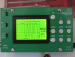
Just remembered that I got a cheap little LCD oscilloscope kit a few years ago. This is what it's showing between GND and the output of the optocoupler. X-axis is 0.5ms per div, Y-axis is 1V per div. It's updating at the same rate that the GPS is set to repeat (once per second) with virtually no jitter. Obviously this just the first part of the signal, zooming out means the peaks are so jumbled together that the low resolution display is just a mess of dots.

Seems to me that is what I should be expecting with the signal voltage being 0-5V and identical data being transmitted once per second.

Optocoupler Output.jpg
 

Elbows

Member
Joined
24 Dec 2016
Messages
137
Visit site
Rogershaw;6404742 these convert TTL to RS422 which is true NMEA signal spec. [url said:
https://www.ebay.com/itm/1-2-5-10PCS-MAX485-MAX485CSA-RS-485-TTL-to-RS485-Converter-Module-For-Arduino-/302163389470?var=&hash=item465a576c1e[/url]

The specs say 5V digital level but the GPS module outputs 2.9V, so presumably I should use the optocoupler to drive this converter as it's outputting 5V. There's going to be quite a daisy chain of bits and bobs, but they all use tiny amounts of power so as long as it works it doesn't matter.

The RS422 spec says that a 120-ohm resistor should be used to terminate the
receiving end of the line. What does that actually mean?
 
Top