How to test a solar panel that has THREE output wires

Ric

Well-known member
Joined
8 Dec 2003
Messages
1,723
Visit site
Hello,

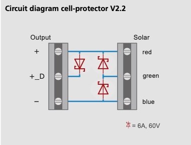
I have a Solara M series solar panel which has three wires from iit (red/blue/green) going into a "cell protector" box, which is just a collection of diodes, then two wires (red and blue) from the cell protector box to the MPPT controller.

Unfortunately the panel is no longer producing much power. How do I test the panel separately from the cell protector? Anybody know what the correct voltages between red/green and blue should be?
 

cpedw

Well-known member
Joined
1 Jun 2001
Messages
1,282
Location
Oban
Visit site
If you were able to sketch the circuit of the cell protector, then I expect one of the sages of this forum could give an informed guess what to look for.
 

lustyd

Well-known member
Joined
27 Jul 2010
Messages
12,398
Visit site
I imagine they are the normal three connection points just with external diodes so you’ll have a wire at each end and one for the mid point between two strings. The diodes will bypass one string each out of the usual two strings. To test you’d need to find which wire is which, in the sun this can be done with a voltmeter and you’ll get -9, +9, -18 or +18 volts depending where you connect on the three wires (assuming it’s an 18v panel).

Lots of assumption in there based on normal panels, I didn’t even Google yours!
 

Ric

Well-known member
Joined
8 Dec 2003
Messages
1,723
Visit site
Sorry should have posted the diode layout - here it is. I get 7.5v green to blue, about 6v (sometimes) red to blue.
 

Attachments

  • Image 01-10-2023 at 17.20.jpg
    Image 01-10-2023 at 17.20.jpg
    22.8 KB · Views: 5

lustyd

Well-known member
Joined
27 Jul 2010
Messages
12,398
Visit site
The voltage should be the same, although some of theirs have odd numbers of cells. Those numbers are low though your open circuit voltage (red to black) should be about 22V so each side should be 11V (this is panel specific and should be on a label on the back of the panel).
 

VicS

Well-known member
Joined
13 Jul 2002
Messages
48,520
Visit site
Hello,

I have a Solara M series solar panel which has three wires from iit (red/blue/green) going into a "cell protector" box, which is just a collection of diodes, then two wires (red and blue) from the cell protector box to the MPPT controller.

Unfortunately the panel is no longer producing much power. How do I test the panel separately from the cell protector? Anybody know what the correct voltages between red/green and blue should be?

The voltage should be the same, although some of theirs have odd numbers of cells. Those numbers are low though your open circuit voltage (red to black) should be about 22V so each side should be 11V (this is panel specific and should be on a label on the back of the panel).
If the back of the panel is inaccessible or the label missing/illegible see below

Measure the open circuit volts and the short circuit current between the red and blue wires with the panel in full sum and disconnected from the cell protector.
Obviously in the UK at this time of year the solar irradiance will fall well short of the STC conditions

1696191097686.png
 
Last edited:

Neeves

Well-known member
Joined
20 Nov 2011
Messages
13,103
Location
Sydney, Australia.
Visit site
We had Solara flexible panels, 2 0ff. The first 2 were replaced under warranty. The replacements lasted about 10 years. They were nicely made with a stainless steel sheet on the back but the panels failed as a result of corrosion creeping under the transparent polymer coating used as the cover. They were expensive, I was not greatly impressed. Since then you can buy cheap flexible panels from a variety of sources, all made in China, and we replaced with a long 150w panel - which is now about 5 years old and was still working 6 months ago.

Jonathan
 

William_H

Well-known member
Joined
28 Jul 2003
Messages
13,987
Location
West Australia
Visit site
Testing of voltage with a digital volt meter (multimeter)has limitations. The current drawn in the test is so tiny (high resistance volt meter) that readings can be unreliable. Simply because a bad connection like corrosion can allow enough current through to show on the volt meter but nothing through in real life.
So as said with panel in the sun connect an amp meter across red to green and green to blue. You should get a current in the range of panel watts divided by 20. Or any current 50% of that figure would be good. (in limited sun etc) If this test fails you may be able to see corrosion under the transparent cover which is cause of failure.
Now to a newby it would seem sacrilege to short out a solar PV panel but unlike say a 12v LA battery, with huge current supply cpability, a solar panel has a high internal resistance. Which naturally limits current produced so no harm done. In fact best way to test the panel. ol'will
 

lustyd

Well-known member
Joined
27 Jul 2010
Messages
12,398
Visit site
connect an amp meter across red to green and green to blue
just be careful, most standard meters don't take a lot of current. I think all of mine have a 10A fuse. I think you'd also need something to consume amps to get a reading anyway. Solar panels don't work like batteries.
 

andsarkit

Well-known member
Joined
27 Aug 2015
Messages
1,257
Location
Dartmouth
Visit site
just be careful, most standard meters don't take a lot of current. I think all of mine have a 10A fuse. I think you'd also need something to consume amps to get a reading anyway. Solar panels don't work like batteries.
Of course battery short circuit current is only limited by it's internal resistance. Solar panels atre limited by the current produced from sunlight so is limited by the size and efficiency of the panel. All the panels listed above have short circuit currents well below 10A so will be quite safe to measure the sort circuit current with a usual meter. Solar panels do not store charge so there will be no surge when you make the measurement.
If you can't get readings of voltage and current similar to the specification in bright sunlight the the panels have failed.
 

VicS

Well-known member
Joined
13 Jul 2002
Messages
48,520
Visit site
Testing of voltage with a digital volt meter (multimeter)has limitations. The current drawn in the test is so tiny (high resistance volt meter) that readings can be unreliable. Simply because a bad connection like corrosion can allow enough current through to show on the volt meter but nothing through in real life.
So as said with panel in the sun connect an amp meter across red to green and green to blue. You should get a current in the range of panel watts divided by 20. Or any current 50% of that figure would be good. (in limited sun etc) If this test fails you may be able to see corrosion under the transparent cover which is cause of failure.
Now to a newby it would seem sacrilege to short out a solar PV panel but unlike say a 12v LA battery, with huge current supply cpability, a solar panel has a high internal resistance. Which naturally limits current produced so no harm done. In fact best way to test the panel. ol'will
Agreed this can make a fool of you when testing generally for power and is why I often suggest that a test lamp can be more helpful but in this case we want to read the voltage at as close to zero current as we can. The short circuit current test will reveal any poor connections.
 
Top