JUSTINHALEWOOD
Active Member
Hi All,
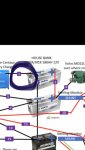
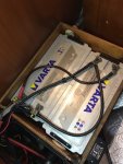
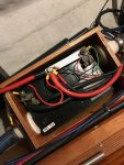
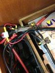
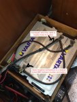
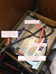
Having bought our boat a year or so ago, I'm now trying to get to grips with the electrics. As part of this we are planning to install solar panels and an improved battery monitoring system. We have an Ampair wind generator and 2x Varta 12v 180 Amphour house batteries currently and will be assessing their health also.
We're trying to start with the installation of a Victron Energy Battery Monitor (BMV-712 Smart). However, I've already hit the limit of my current understanding and was hoping for advice from the forum. Please find a summary of the current set-up and wiring diagram (work in progress) below - thank you for your help!
- The Varta house batteries are wired in parallel. I have also included the connection to the start battery also (Numax 12v 70ah).
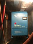
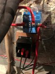
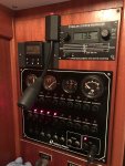
- There are two separate shunts fitted to one of the Vartas batteries and one to the Numax. I believe these are connected to the Sterling Battery Monitor currently installed (I want to replace to the BMV to access the smart functionality like 'remaining time').
- Please see other connections below. I have yet to trace all wires as they go into the interior of the boat - I'm planning to do this in the next few weeks.
Where should I put the BMV? Is it just a case of replacing the existing shunt?
Thank you for any help!
Justin

Having bought our boat a year or so ago, I'm now trying to get to grips with the electrics. As part of this we are planning to install solar panels and an improved battery monitoring system. We have an Ampair wind generator and 2x Varta 12v 180 Amphour house batteries currently and will be assessing their health also.
We're trying to start with the installation of a Victron Energy Battery Monitor (BMV-712 Smart). However, I've already hit the limit of my current understanding and was hoping for advice from the forum. Please find a summary of the current set-up and wiring diagram (work in progress) below - thank you for your help!
- The Varta house batteries are wired in parallel. I have also included the connection to the start battery also (Numax 12v 70ah).
- There are two separate shunts fitted to one of the Vartas batteries and one to the Numax. I believe these are connected to the Sterling Battery Monitor currently installed (I want to replace to the BMV to access the smart functionality like 'remaining time').
- Please see other connections below. I have yet to trace all wires as they go into the interior of the boat - I'm planning to do this in the next few weeks.
Where should I put the BMV? Is it just a case of replacing the existing shunt?
Thank you for any help!
Justin

") ).
).