BenMurphy
Active Member
I've just bought a 1991 Hunter Horizon 27, and I'm struggling to understand the battery set-up slightly. There are two batteries, but both feed into a very tight bundle of cables that run through the cockpit floor and up past the engine compartment, so it's impossible to follow the circuits without taking the whole bundle apart, which is going to take more effort that I'm willing to put in at the moment. Also I'm not confident about putting all back together competently!
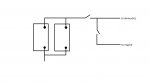
Basically there are two batteries, that I assume to be the domestic and engine batteries. There are two separate isolators. The left isolator operates the domestics, and is pretty simple - if it's on they work, if it's off they don't.
The right isolator operates the engine starter battery (I think), but the engine will only start if both the isolators are set to on i.e. if the engine isolator is on but the domestic is off, the engine won't start. See my dodgy sketch which helps explain.
My assumptions are thus these - please affirm or challenge them!
- This suggests that the circuits to both batteries are running parallel
- If so, the boat will start via the engine battery if the domestic battery is flat, but both circuits would still need to be open
- This suggests that the alternator will charge BOTH batteries if both circuits are open when the engine is running
I believe I can test the last assumption using a multimeter when the engine is running and checking if both batteries are registering > 13V. Is there any way I can confirm the other assumptions without picking apart the big cable mess?
I'm pretty new to this so please help if I've completely misinterpreted the whole thing!