Help please with 1GM10 alternator issue.

niallw70

Active Member
Joined
13 Apr 2011
Messages
45
Location
Burntisland
Visit site
I have a rebuilt Yanmar 1gm10. Since overhaul starts ok but the charge light staying on when engine tested.
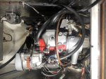
Im confused about how alternator is wired up, or how to test voltage/ current output in confined space of engine bay.
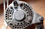
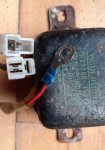
At rear of alternator there are 4 posts for spade or ring cable cable terminations. Also there is three pin socket with pins labelled E, earth?, F, N. The mating plug goes to an external voltage regulator. VR manufacturer NIPPONDENSO, serial no 0260003861.
There are zero markings or serial model/ numbers on the casing of the alternator itself.
Is this a standard Yanmar alternator?
35 or 55A? How should this thing be wired up? No markings of any kind to indicate +,-, Excitation on the back of the alternator.

I will try supplying a photo in this post. Ive had problems with uploading pictures before to this forum. What camera settings should i use? Even on lowest quality pixels, the attachment rejected.
 
Here is a pic of external voltage regulator. Confusingly its wired with a 2 pin plug i thought might be for tachometer, which i dont have. As far as i can remember its always been left unconnected. Also the 3 pin plug to mating socket on alt. Also red cable, where should this go? I assumed +ve terminal on alt, but now not sure.
 

Attachments

  • signal-2021-12-11-12-00-17-744.jpg
    signal-2021-12-11-12-00-17-744.jpg
    158.7 KB · Views: 9
Do you have a multimeter and know how to use it?
The simplest way to check is measured the voltage of the battery with the engine off and then with the engine running, this will tell you if it is charging.
A high probability is that the fault is carbon brushes if not charging
 
That doesn't look like the standard alternator which has an internal regulator. I'm not sure if these circuit diagrams will help.
There is an 'Alternator Handbook' on the net which might have some more relevant information.
1639227840692.png
1639227907576.png
 
That doesn't look like the standard alternator which has an internal regulator. I'm not sure if these circuit diagrams will help.
There is an 'Alternator Handbook' on the net which might have some more relevant information.
View attachment 127104
View attachment 127105
It doesnt matter which alternator if it worked before and it's not now.
The top circuit diagram looks to be correct with your photo.
First check if it is charging or it isn't by watching the voltage on the battery terminals wit a multimeter
 
It might be worth checking with the plugs in place and the ring terminal disconnected if the ignition light comes on when the key is turned. If it does then start the engine and see if there is a voltage between the rusted stud and alternator body. If there is then maybe this is where the ring terminal should be connected.
 
Maybe you can zoom in on this , i can take a more detailed alternators pic tomo if still needed ( sor , dont know what any of the wires are )
 

Attachments

  • C2CE64B5-49EE-4C18-BB75-BEACC1F95E0C.jpeg
    C2CE64B5-49EE-4C18-BB75-BEACC1F95E0C.jpeg
    118.4 KB · Views: 17
Thanks for all the replies, I think you've cracked it for me. The sketch done by Andsarkit fits with the arrangement I have. I'm wondering where you got this?
"The Alternator Handbook", is this online? If so please send the link where I can find it.
 
Hi, again. I think I've found The alternator Handbook as pdf file on SCRIBD website.
They are offering free download if I signup for 30 day free trail. I'd rather not give my details to yet another online content provider, if someone is willing to send this file to me, PM me and I will supply my email address.
Many thanks in advance.
 
Online here:Alternator handbook
The first link I found came up as a security risk so I hope this one works.
It is handwritten but contains lots of information on different systems. Page 76 and 210 relate to your setup.

If you pm me I can send it to your email.
 
Many thanks for the link. I'm able to download and view, no problems.
I feel one step nearer diagnosing my charging fault. But I'm not finished with this thread yet. I'll let you know how it's going when I get the chance to test.
 
What you should do to make life easy is to make up a 12 volt test lamp by soldering two wires to a filament bulb of about 20 watts then wrap the cap and connections in self amalgamating tape. You will find it very useful in circumstances like this. I am always losing these to dockmates. :cool:
 
What you should do to make life easy is to make up a 12 volt test lamp by soldering two wires to a filament bulb of about 20 watts then wrap the cap and connections in self amalgamating tape. You will find it very useful in circumstances like this. I am always losing these to dockmates. :cool:
Or get one for a few £ in halfords
 
Top