PaulRainbow
Well-Known Member
In post #88 i said "If you have the usual TAMD41x engines and standard panels on the flybridge you would not have had oil pressure gauges." The Mercruiser option is rare and without any info about engine from the OP, i based post #88 on the more "normal" Volvo engines.
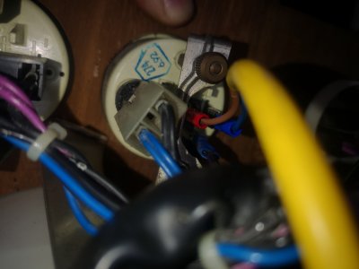
The statement in post #90 that "They are current measuring devices ( milliammeters )" is incorrect. The TAMD41 series (along with most/all) Volvos of the era use VDO resistive senders.
These senders are available in single or dual station. The standard engine panel for the TAMD41 does not have oil pressure gauges on the flybridge, so the sender would be single station. The panel does have a key switch, the same as the lower helm.
Changing the sender to a dual station one would be a pointless waste of money, and pretty stupid, as it would mean that both helm stations would need to be powered up all of the time. You cannot operate the boat from both stations at the same time, if one wants to change from one helm to the other there is a procedure to hand control to the other station, this varies from boat to boat. With my boat, for instance, the engines need to be taken out of gear at the helm in use, or the control levers cannot be operated at the other helm.
So, with the flybridge gauges wired in parallel one simply turns the key switch on at the helm one wishes to use and everything just works. If one wants to move to the other helm, ones takes the engines out of gear and turns the key switch off, turning the key switch on at the other helm and engaging the gearbox.
It's that simple.
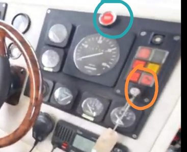
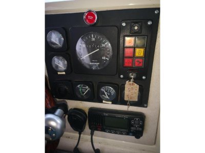
The OP has subsequently revealed that he has Mercruiser engines, this doesn't necessarily change the above, but it would be helpful to see a picture of the flybridge helm at to know how/if the engine can be stopped/started from the flybridge.
Both gauges should still be wired in parallel. If the flybridge originally had oil pressure gauges, they should work correctly. If not, one would normally only power up the helm in use, as above. The OP states there is no key switch on the flybridge, having no way to start/stop the engines from the flybridge would be unusual, but if that's the case, there is still no need for a changeover switch at the flybridge. Fitting one would mean running a wire from the engine harness to the flybridge and back again, pointless. It would make more sense to fit a changeover switch at the lower helm. Or, fit a simple on/off switch at both helms, only turning on the one that is needed.
EDIT : A more elegant solution to changing helm power to the instruments (in the absence of key switches on the flybridge) would be to fit a latching relay at the lower helm. Cut the positive wire that goes to all of the instruments and connect it to the relay, connect another wire that goes to the flybridge helm and powers all gauges there. Connect a negative to the relay. Fit momentary on switches/buttons at both helms to supply power to the relay coil. Pressing either button will change the sate of the relay, turning one helm off and the other on.
The statement in post #90 that "They are current measuring devices ( milliammeters )" is incorrect. The TAMD41 series (along with most/all) Volvos of the era use VDO resistive senders.
These senders are available in single or dual station. The standard engine panel for the TAMD41 does not have oil pressure gauges on the flybridge, so the sender would be single station. The panel does have a key switch, the same as the lower helm.
Changing the sender to a dual station one would be a pointless waste of money, and pretty stupid, as it would mean that both helm stations would need to be powered up all of the time. You cannot operate the boat from both stations at the same time, if one wants to change from one helm to the other there is a procedure to hand control to the other station, this varies from boat to boat. With my boat, for instance, the engines need to be taken out of gear at the helm in use, or the control levers cannot be operated at the other helm.
So, with the flybridge gauges wired in parallel one simply turns the key switch on at the helm one wishes to use and everything just works. If one wants to move to the other helm, ones takes the engines out of gear and turns the key switch off, turning the key switch on at the other helm and engaging the gearbox.
It's that simple.
The OP has subsequently revealed that he has Mercruiser engines, this doesn't necessarily change the above, but it would be helpful to see a picture of the flybridge helm at to know how/if the engine can be stopped/started from the flybridge.
Both gauges should still be wired in parallel. If the flybridge originally had oil pressure gauges, they should work correctly. If not, one would normally only power up the helm in use, as above. The OP states there is no key switch on the flybridge, having no way to start/stop the engines from the flybridge would be unusual, but if that's the case, there is still no need for a changeover switch at the flybridge. Fitting one would mean running a wire from the engine harness to the flybridge and back again, pointless. It would make more sense to fit a changeover switch at the lower helm. Or, fit a simple on/off switch at both helms, only turning on the one that is needed.
EDIT : A more elegant solution to changing helm power to the instruments (in the absence of key switches on the flybridge) would be to fit a latching relay at the lower helm. Cut the positive wire that goes to all of the instruments and connect it to the relay, connect another wire that goes to the flybridge helm and powers all gauges there. Connect a negative to the relay. Fit momentary on switches/buttons at both helms to supply power to the relay coil. Pressing either button will change the sate of the relay, turning one helm off and the other on.
Last edited: