CapPugwash
Well-Known Member
Hello matey-boaty-peeps ")
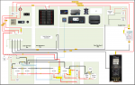
Currently re doing the power distribution on my Vancouver 32 and am looking for some advice on fuse placements, sizing, life and the meaning of everything.
My batteries, starter motor and main busbars are all already connected with 35 mm2 Tinned OceanFlex and I am planning to do the rest in 16 mm2. I have highlighted the fuses in yellow. What do you think?
EDIT : Updated Diagram to show revised fuse placement as per suggestions in this thread.
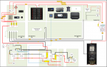
Attachments
Last edited:

