Full Engine Monitoring System

superheat6k

Well-known member
Joined
10 Jan 2012
Messages
6,711
Location
South Coast
Visit site
My mistake. It seems that the T100 is 100k @ 25degC, so specific to this manufacturer. There are some advantages in using standard sensors which are easier to incorporate with a huge range of fitments.
These are available to me at cost from the supplier / manufacturer and I know they are very reliable.

I have bought a suitable plastic box enclosure with a clear lid for the PCBs. This will mount on a bulkhead within the engine bay. I am procuring the necessary hardware now.

For the flow I am considering putting a smaller flowswitch in the bleed line to the shaft seal, which takes off from the feed pipe between the gear oil and main coolers, but I will need to check for adequate flow at idle. However, if necessary I could build a logic loop preventing an alarm below a certain RPM. I can get a brass bodied switch for less than £10.
 

superheat6k

Well-known member
Joined
10 Jan 2012
Messages
6,711
Location
South Coast
Visit site
By way of an update, I have now obtained all the basic transducers and converters to process the various input data into readable 0-5VDC signals. I am incorporating these into the engines as part of the re-assembly following my engine failure.

Some will need some testing to set up e.g. RPM pulse count, conversion of the alternator amps. I also need to decide where is best to measure certain temperatures, for which I expect too use small copper sensor tubes with a squirt of heat transfer paste within. We mount these with heavy duty epoxy for the machines I work with, so this should work OK, but I am using immersion sensors where I can, and have found some adaptors to allow the oil temperature to be directly measured inside the sump pan.

My American colleague has established the method of flow monitoring via the smaller shaft seal bleed line works very effectively right down to idle speed. I have received my brass flow switches and will be fitting these shortly.

Still working on the display options. I have tried a cheap Android tablet, but can't make it run Linux properly, so I am likely to pay out a bit more for a Windows tablet. There are some Bacnet to NMEA2000 converters available, but the range of sentences NMEA2000 offers, and that plotters can display is severely limited, and way below the list I wish to monitor.

I can already display the data in a table form, with separate external alarm devices, such as flashing lamps and sirens. But table format data is not ideal on a moving vessel that also needs to be navigated.

The total list so far will add ~50 or so new cables inside my engine room. I have acquired the box to put the hardware in and know where to mount it, but the engine rebuild has taken up all my available time so far.
 

superheat6k

Well-known member
Joined
10 Jan 2012
Messages
6,711
Location
South Coast
Visit site
My lockdown project following the engine repair through the Autumn has been slowly developing, alongside several home projects.

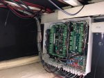
The monitoring system is now 80% installed, and yesterday I powered the system up for the first time, and I am now resolving a few alarm programming issues. I still have several sensors to fit, including several I shoud have fitted before I closed the flooring up, however my slender 17 year old Daughter should come in very handy for getting these into position !

I have set up a series of Major and Minor alarms, with a further set of 'External' alarms for remote monitoring of the boat via a 4G router. This will also have two controllable cameras connected.

The Major alarms are: Lost water flow; high exhaust temperature; low oil pressure for each engine plus hot engine room. These are annunciated with a very loud 120 dB siren on the flybridge, with a press button to silence the alarm, with a prominent LED for each engine.

If one of these sounds first priority after safe navigation will be to stop the affected engine.

The minors are a whole array of engine pressures and temperatures, plus an engine room warm alarm. Annunciated by the same siren sounding at 4 second intervals.

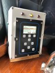
A lower dB siren is also provided in the Cabin lower helm position, alongside the primary access display. Any alarm will be shown in the display window as it happens.

Once I have all the various sensors (32 in total), in position I can then look at the wireless link to a Windows tablet on the flybridge, which will have the various parameters displayed as a set of gauges, and touch sensitive indicators.

The main panel still needs the clip top covers affixing and some tidying of the cables.

The button on the side of the display / keypad silences the siren.

IMG_5062.jpgIMG_5068.jpg
 

vas

Well-known member
Joined
21 Jun 2011
Messages
7,933
Location
Volos-Athens
Visit site
well done Trev!
good luck with the fine tuning, only took me a couple of years to have the systems as I had them in my mind :) Lockdown was instrumental.
Now working on the next step, got a router onboard and a raspberry pi with signalK and all my data from the N2K bus goes on my office server and then through grafana have all the info visible on my browser!

V.
 

superheat6k

Well-known member
Joined
10 Jan 2012
Messages
6,711
Location
South Coast
Visit site
I can obtain all the data as Bacnet or Modbus, which I think can be converted to NMEA2K at least for sentences it supports. But I don't have a plotter that can display NMEA2K, so I will be going for a Windows tablet. This system is Windows only, so the only way to view it in a Mac or Ipad is via another PC and then Teamviewer or some other remote desktop platform. I am going to use ethernet over wifi, so I don't have to have any cables onto the Tablet, which will mount inside an Overboard casing.
 

vas

Well-known member
Joined
21 Jun 2011
Messages
7,933
Location
Volos-Athens
Visit site
so, are you actually going to write code to display them?
there are many ready made solutions by the looks of it that take various info (I think they also take Modbus - never played with it!)
openplotter, or signalk could be helpful to get decent displays with a few clicks

V.
 

superheat6k

Well-known member
Joined
10 Jan 2012
Messages
6,711
Location
South Coast
Visit site
so, are you actually going to write code to display them?
there are many ready made solutions by the looks of it that take various info (I think they also take Modbus - never played with it!)
openplotter, or signalk could be helpful to get decent displays with a few clicks

V.
The makers have a graphics package, that I intend to learn to use. I am working with my sales contact there as he has the same engines in his boat in Florida (and slightly better weather and destinations - Fort Myers, Sanibel Island is beautiful. Bahamas are a couple of days away).
 
Top