Electrical puzzle, need some help

stone beach

Active Member
Joined
27 May 2011
Messages
64
Visit site
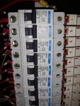
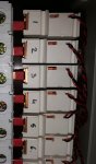
The electrical control system on my boat uses a touchscreen to control a PLC which eventually switches the pictured devices to power on or off the circuit breakers for the various circuits.

I am calling them remotely controlled isolators ... my term, probably wrong.

I think they latch in position, position is indicated by the small red lever you can see in the photo, the small red lever also allows them to be switched on and off by hand. I haven't turned the PLC off to test the latching.... scared it won't restart !

I have tried many searches to find these devices on Google and spent several hours with catalogues etc but can't find anything that looks or sounds similar.

Does anyone have any idea what to look for or where I might find them? tried many combinations of bistable, power, relay, isolator, remote with no success, obviously I'm missing an important term....

I am trying to locate technical specs for them.

I know, it's a ridiculously complicated way to organise a switch panel but that's what it is.
 

Attachments

  • 20180730_210422 small.jpg
    20180730_210422 small.jpg
    67.2 KB · Views: 1
  • remotely operated isolators.jpg
    remotely operated isolators.jpg
    442.3 KB · Views: 1
Unless the PLC control makes any relevant difference which I'm missing, they seem to do the same job as the bistable impulse relays which I've got on my boat.
Mine are made by Merlin Gerin, and they close/open the contact of a specific light line, when they receive an impulse from any of the multiple pushbuttons controlling that light.
They look a bit different because on top of the manual on/off lever (akin to your small red one) they have a second switch that allows to connect/disconnect each of them individually from being remotely controlled, which is a handy feature. I can't tell you the exact model by heart now, but I can find out.

Anyway, it's very weird (even illegal, I suspect!) for an electrical component not to have any specs/references stamped on it. Did you check also the rear side?
Besides, am I right in understanding that those relays (if that's what they are!) are connected upstream of the breakers? If so, that's also a weird installation, imho.
Who is the boat builder, if you don't mind me asking?
 
Besides, am I right in understanding that those relays (if that's what they are!) are connected upstream of the breakers? If so, that's also a weird installation, imho.
Who is the boat builder, if you don't mind me asking?

why is this odd P?
if they are rated MORE than the breakers it's absolutely fine (and that's how my BMS is setup.
Unfortunately the relays used in mine are completely different and surface mounted on a custom 8U rail box thing so I cannot help the OP. I would have thought it's one of the large cos doing them, maybe you're searching using the wrong terms???

good luck to the OP

V.
 
MapisM
Thank you for your response.
I agree that the PLC probably does not do anything significantly different to what a p/b could, but I don't know (yet) whether the PLC maintains the operating signal or just sends a pulse.
Part of the reason I am looking for the spec for the device in question is to understand what I could use instead of the PLC, i.e. a p/b or a switch, to drive it. It seems fairly obvious it will be the twisted r&b pair that are causing the action just now, if all else fails I can of course break into these and measure what is happening.

I will go through MG and other websites and see what I can find now including "impulse" in my search terms, I haven't used that so far.

I agree there should be data marked on the device but I am not able to access it to check that (currently I am 6,000 miles or so away from the boat) .... and in the meantime I am trying to engineer a replacement control system without a PLC.

The system as fitted works fine just now and I am happy enough with it's operation but I would like to develop a contingency for obvious reasons. I took many photos before I left the boat with that exercise in mind but I didn't anticipate this particular device being so difficult to identify.

Regarding the location of the device in the circuits, they are configured as isolators and are therefore upstream of the breakers.
I guess there is some kind of bus rail behind them forming a common input to the hidden side of each one and you can see an outlet "bus" section from each to it's corresponding circuit breaker (with red sleeve over it).

I have (of course) contacted both the boat builder and the electrical system / panel builder to try and get information, so far without success.
 
why is this odd P?
if they are rated MORE than the breakers it's absolutely fine (and that's how my BMS is setup.
Unfortunately the relays used in mine are completely different and surface mounted on a custom 8U rail box thing so I cannot help the OP. I would have thought it's one of the large cos doing them, maybe you're searching using the wrong terms???

good luck to the OP

V.

Vas,

posts crossed so to speak!!

You will see more data in my last post, can you give me some terms to use ?

so far I've used combinations of bistable, power, relay, isolator, remote and will now add impulse....

I wonder if they are individual pieces or combined on a bus section ? never seen anything like them before
 
Try latching relay - need to source a replacement for my Targa 52 as wel as they seem to stick. Axon components have on on their website with a 12V coil supposed to work on a 24V system as well but not getting much joy from them to confirm this. Have found some alternative online but with different wiring arrangements. Latching relay turns up a selection.
 
Try latching relay - need to source a replacement for my Targa 52 as wel as they seem to stick. Axon components have on on their website with a 12V coil supposed to work on a 24V system as well but not getting much joy from them to confirm this. Have found some alternative online but with different wiring arrangements. Latching relay turns up a selection.

Axon normally v helpful. Give them a call and ask for Barry if you've not already done so.
 
Try latching relay - need to source a replacement for my Targa 52 as wel as they seem to stick. Axon components have on on their website with a 12V coil supposed to work on a 24V system as well but not getting much joy from them to confirm this. Have found some alternative online but with different wiring arrangements. Latching relay turns up a selection.

rlw,

BINGO !!

I had tried the AXON website without success, I must have been doing something wrong

I will research more later but sure thats the one

Thanks to all for helping
 
Vas,

posts crossed so to speak!!

You will see more data in my last post, can you give me some terms to use ?

so far I've used combinations of bistable, power, relay, isolator, remote and will now add impulse....

I wonder if they are individual pieces or combined on a bus section ? never seen anything like them before

OK, now that you found how they are called :D
just keep in mind that I expect them to be two individual things. The breaker below, and the "thing" which obviously has a copper "blade" (the top of which is probably nicely covered with red heat-shrink) that fits on the output (top) of the breaker. If you undo the top screw on the breaker, you should be able to pull the thing up. Therefore I doubt they are rail equipment as there wouldn't be a way to detach them from the rail! Not to mention that you don't get el. boxes (unless heavily customised) that have rails so close together. That's my understanding from this tight arrangement but we don't have a pic on what's happening on top of the "thing" too dark in the top pic to figure out. There should be the (+) cable going to the device somewhere there.

TBH, I don't see what exactly you're after overall. If the system works, just get a couple of these as spares and enjoy the boat!
As I said on my previous post, I have such latching relays running throughout my house which is occupied 24/7 for the last 15yrs with ZERO problems, don't see how you're going to have problems. And anyway if you do, there's the failback method of pulling up and down the small red bars on each one...

cheers

V.
 
why is this odd P?
if they are rated MORE than the breakers it's absolutely fine
Agreed, but why not put the relays downstream of the breakers and include them in the protected section of each line anyway?
Btw, that is how they are arranged also in my 100% bus cabled home (done by a specialized company, not my own effort :o), aside from my boat.
Apropos, in the meantime it popped to my mind that I had a pic where the things that I have onboard are visible, scheme included - see below.
At home, I have somewhat more sophisticated and dimmable KNX actuators, but aside from being SW programmable, essentially they do the same job.
Good point ref. the OP ones unlikely being DIN rail mounted, that's another thing I struggle to see a reason for.
Brit boat, surely? I'll get my coat... :rolleyes: :p
ZzjccjGu_o.jpg
 
Top