DPH trim senders

frocco

New member
Joined
12 Mar 2023
Messages
10
Visit site
Hello, I have been struggling with a trim issue on my Formula 400 SS with twin D6 DPH. It has B transom assembly’s. When I trim all the way up, the port reads 40 deg the starboard reads 29 deg. That are both up
To their max tilt. When I calibrate max tilt stays at 40 and 29, all the way down reads -5 on both. As I trim up they do not stay in sync physically, the computer will lift them so they show equal on the guage but are physically at different positions. I don’t have a spare sensor to read with a meter to know what the typical full range resistance is from end to end. If you know the boat, I have no access to the senders without some tear down. If I decide to go after a sensor I would like to know which one is out of spec. Hoping that removing the cooler will give me some access. Any help or onsite would be much appreciated.
 

volvopaul

Well-known member
Joined
1 Apr 2007
Messages
8,888
Location
midlands
hotmail.co.uk
Hello, I have been struggling with a trim issue on my Formula 400 SS with twin D6 DPH. It has B transom assembly’s. When I trim all the way up, the port reads 40 deg the starboard reads 29 deg. That are both up
To their max tilt. When I calibrate max tilt stays at 40 and 29, all the way down reads -5 on both. As I trim up they do not stay in sync physically, the computer will lift them so they show equal on the guage but are physically at different positions. I don’t have a spare sensor to read with a meter to know what the typical full range resistance is from end to end. If you know the boat, I have no access to the senders without some tear down. If I decide to go after a sensor I would like to know which one is out of spec. Hoping that removing the cooler will give me some access. Any help or onsite would be much appreciated.
It's possible the clamp bolt on the trim pin is loose not allowing the full rotation sweep from down to up or the sender is faulty , if you have good access swap the senders and re calibrate also while the senders are out try to twist the pins to check for play .
I say try as most boats are very difficult to get access .
 

frocco

New member
Joined
12 Mar 2023
Messages
10
Visit site
Paul, thanks for your response, been a little busy to respond. After a little more research and a mirror I can report this. 1) I can see the sensor with a mirror and after pulling off a few cooling hoses I think I can reach the starboard sensor. I can’t see it but I can put my hand on it. It is the newer style sensor thankfully. I am confident I can remove and replace it.
2) After seeing that Volvo charges 295 for a sensor, and I am not sure mine is bad, looked close at a transom assembly picture I have and noticed that it is a standard Bosch throttle position angle sensor that Volvo riveted to a base plate and added a shaft. I ordered the sensor at rock auto for 22 bucks. This way I can test the resistance as I rotate it and verify mine. I was also able to find the pdf of the sensor that showed the resistance specs pinout and liner graph. My plan is when it comes, I will test the resistance rates and ranges on both of mine and the new sensor. If I think the starboard one is off, I will remove it and compare against the new one. And either reinstall or replace with the new one using vp’s instructions.
 

papparazzi

Member
Joined
5 Jan 2023
Messages
34
Visit site
@frocco I have similar problems with my D4-260 paired with DPH-A. Both indicators are no longer reliable and would regularly drift up or down resulting in an alarm / warning of the power trim. This typically happens if I am maneuvering with frequent change of direction. The warning itself however does not impact the boats operation.

Yesterday I run into the next problem whereby a major error was registered (powertrim failure) as MID187 PPID 401 FMI 4 which seems to be undervoltage of the sensor outside the specification which also resulted in my trim angle showing 56 with BEACH which then prevented me to start the engine. Now that's a totally different world of (sensor) pain :cry: as even unplugging the sensor didn't solve this situation for me. I traced the sensor harness back to the trim pump harness back to the engine port side bracket (transmission interface) for the cable harness. The plug at the port side bracket had some moisture in it which eventually (so the theory today) may have shorten or at least impacted the signal in such a way that it didn't work. After some playing around with these cables and power cycling the ECUs (batter switch off / on) it eventually went back to a normal reading. :eek:

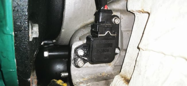
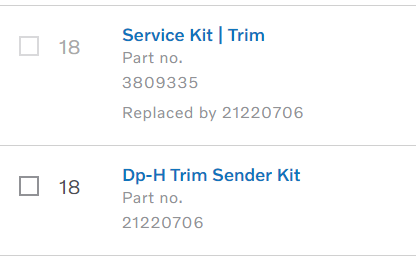
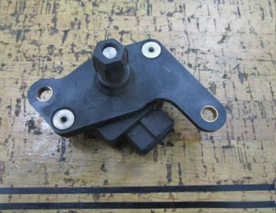
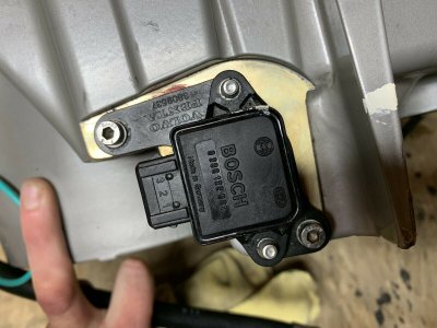
Now, I need to investigate and fix the problem permantelty as a unreliable trim sensor is not much fun. I found out there are 300 USD (gen 1) and 900 USD (gen 2) sensors and I am unclear which one I have. You mentioned you have the new one - can you have a look and confirm it looks like mine attached ? Would you know the part number ?

Based on Volvo parts for my engine I am supposed to have the old one (300 USD) but it seems they can be interchanged with the new one as well (anybody can confirm) ?

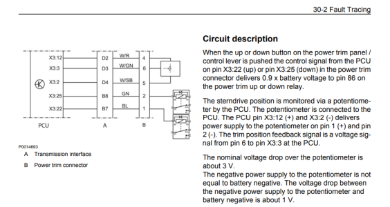
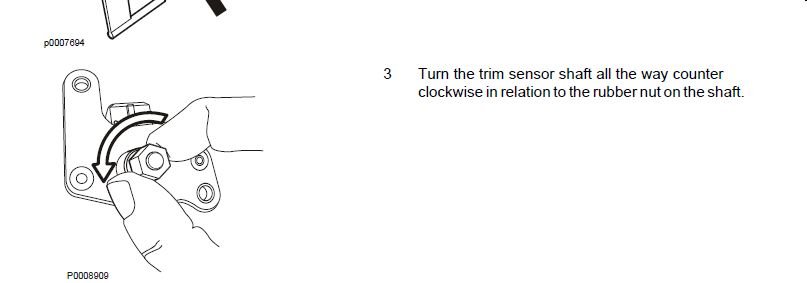
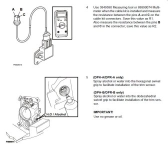
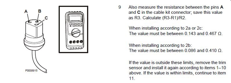
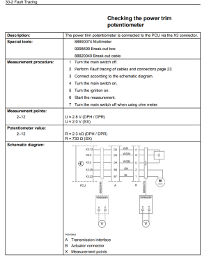
Regarding your 3rd party Bosch sensor - attached some snapshots from the DPH electrical repair manual which mentions voltages - maybe you check your Bosch falls into the same spec ? Few things to note - sensor expects 5V and not 12V, normal voltage on the return (sense) line is around 3V . To low (<1.2V) and to high (> 4.4V ) of voltages will result in EVC errors messages on your display. This also means (to me) that plugging out a defective sensor will still result in a yellow error / warning (MID187 PPID 401 FMI 4) impacting ability to trim (override available) and no correct position to display which very likely means it defaults to 56 BEACH (aka 'worst case') and prevents the engine to start. If any skilled VP mechanic could comment on this (can we plug out the sensor and still start) that would be helpful as misleading statements have been found...


1716178461566.png1716178389005.pngWhatsApp Image 2024-05-20 at 11.42.15.jpeg1716179165298.png
 

frocco

New member
Joined
12 Mar 2023
Messages
10
Visit site
Papparazzi

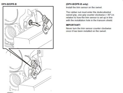
Thank you for the reply. Sorry for the delay!. First off, I was able to blindly remove my sensor. the rubber 6 sided piece that engages inside the transom stayed in but was able to pull it out with a large sheetmetal screw. Once out and armed with the DPH shop manual and Bosch pdf for the sensor I could see that the R values were in spec. I re-installed the sensor following the shop manual and was able to get drive to calibrate correctly and match the readings on the port drive. Either it was installed incorrectly or the shaft of the sensor spun on the rubber "wheel". Hopefully it will not happen again.

As for your statements. It all depends on your transom part number. if your sensor looks like the photo in your post, you have the newer one. The newer one is only 300
the old one is 800. I have dph-d1 drives now but they were originally DPH-A's but it seems that a lot of the DPH-A's came with DPH-B transom shields which is a good thing. Mine included. Most or all dph-a transom assembly's have the old sensor. The bosch angle sensor that I bought for 22 is the same part number and will work but you have to
drill the rivets off the Volvo one, reuse the old shaft, rubber wheel and mounting plate and then pop rivet or screw it together. you have to make sure that it is a flat surface where it mounts on the shield.
 

Attachments

  • Bosch 0280122001 trim sensor.pdf
    261.6 KB · Views: 8

papparazzi

Member
Joined
5 Jan 2023
Messages
34
Visit site
@frocco Thanks for the updates and great to hear you fixed it without actual new parts :) .

I have ordered the BOSCH sensor based on your input and will try to change it on the port side where the access is better. If I understand you correct there will be some kind of shaft and rubber piece which will need attachement to penta backplate to make this work . I will see once I get it. (if you have more pictures would be great if you can post it here)

One other question - you mentioned you have DPH-B Transom shields and you upgraded DPH-A to DPH-D1. That's very interesting - I might need to do the same at some point as the DPH-A are apparently failing easily. I attached my part numbers - I am a right to assume the Transom shield of mine is also a DPH-B variant ?

1718092279829.png
 

frocco

New member
Joined
12 Mar 2023
Messages
10
Visit site
Papparazzi

Based on your transom shield part number, and the picture of your sender, you have a DPH-B shield which I found is a good thing.
I have a picture of the sender as it mounts, I wish I would of took a picture of the back but I did find some.

Chances are when you pull out the sender the rubber piece will stay in the shield. I just used a large sheet mettle screw/lag screw
a little larger than the shaft, cross threaded it into the rubber piece and it pulled right out. Just do mot use something too big
that will damage the wheel. There is a flat on the shaft and wheel so it can only go on one way.

The stock bosch sensor has a female hole for the shaft which means you must use the shaft and rubber wheel from your old one
as well as the mounting plate.

I have not had to do this but , drill out the rivets, and either pop rivet the new sensor on or use flat head screws with a nylock nut
or some threadlocker, just make sure the mounting surface is flush.

if you dont have the shop manual for the drive let me know.

I grabbed some pictures for you from this ebay post.
*90 DAY WARRANTY* 0780 Volvo Penta Trim Service Kit 3818189 | eBay
 

Attachments

  • capture_13062024_082745.jpg
    capture_13062024_082745.jpg
    67.9 KB · Views: 9
  • capture_13062024_081511.jpg
    capture_13062024_081511.jpg
    71 KB · Views: 8
  • s-l1600.jpg
    s-l1600.jpg
    269.9 KB · Views: 9

frocco

New member
Joined
12 Mar 2023
Messages
10
Visit site
FYI, the trim sensor install procedure with the drive on is as follows.

1) Trim drive all the way down.
2) with the sensor out turn shaft all the way clockwise as in step2 picture.
3) measure the resistance as in Step3 pic and lubricate as shown. I used water.
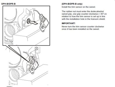
4) insert sensor aprox. 30deg forward and into the 6 sided hole. see pic step4
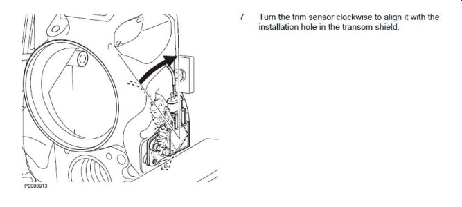
5) rotate counter clockwise so that screw holes align correctly.
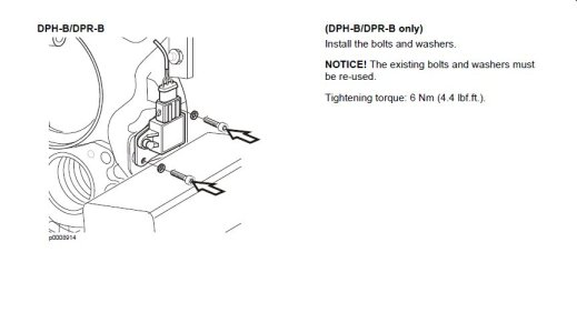
6) secure screws.
7) Measure resistance and use formula to check that mounting was correct. installing with drive on is method 2a
so calculated value should be between .143 and .467 ohms.

you don't have to do the resistance measurements but if you do you will have more confidence that you did things correct.
 

Attachments

  • Step2.jpg
    Step2.jpg
    17.9 KB · Views: 11
  • Step3.jpg
    Step3.jpg
    77.1 KB · Views: 11
  • Step4.jpg
    Step4.jpg
    67.9 KB · Views: 10
  • Step7.jpg
    Step7.jpg
    40.8 KB · Views: 10
  • Step6.jpg
    Step6.jpg
    32.2 KB · Views: 9
  • Step5.jpg
    Step5.jpg
    34.9 KB · Views: 11
Top