DC2DC charger + emergency parallel wiring advice

tymonk

Member
Joined
3 Sep 2022
Messages
54
Visit site
Hi. I want to replace the VSR that came with the boat with a DC2DC charger to keep the 2 batteries (starter + domestic) separated and to apply an AGM-specific charging profile when the alternator is running.

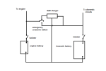
The boat has an emergency parallel switch behind the 2 individual battery isolator switches. I emailed the DC2DC company to ask what would happen to the DC2DC charger if the batteries were paralleled in an emergency. They have said both positives and negatives from the charger should be disconnected to avoid the charger and batteries being damaged, whether the engine was running or not.

Does anybody have any solutions for this? Ideally this could be done through a single switch, and possibly integrated with the emergency parallel switch? I have sketched out a switch that would work (see screenshots) but I don't know if something like that exists. Alternatively, a quadrupel (8 pole?) isolator switch that would just need to be manually switched off before engaging the emergency parallel, but I haven't seen these for marine use. The most I have found are dual.

Any advice or suggestions would be much appreciated! Many thanks.
 

Attachments

  • Screenshot 2023-02-20 at 13.25.33.png
    Screenshot 2023-02-20 at 13.25.33.png
    112.9 KB · Views: 24
  • Screenshot 2023-02-20 at 13.25.54.png
    Screenshot 2023-02-20 at 13.25.54.png
    106.2 KB · Views: 22

Trident

Well-known member
Joined
21 Sep 2012
Messages
2,711
Location
Somewhere, nowhere
Visit site
DCDC normally need energising from the start key etc so if you put a switch in that wire to turn the DCDC off when paralleling the batteries that may well be enough.
 

ean_p

Well-known member
Joined
28 Dec 2001
Messages
3,012
Location
Humber
Visit site
Hi. I want to replace the VSR that came with the boat with a DC2DC charger to keep the 2 batteries (starter + domestic) separated and to apply an AGM-specific charging profile when the alternator is running.

The boat has an emergency parallel switch behind the 2 individual battery isolator switches. I emailed the DC2DC company to ask what would happen to the DC2DC charger if the batteries were paralleled in an emergency. They have said both positives and negatives from the charger should be disconnected to avoid the charger and batteries being damaged, whether the engine was running or not.

Does anybody have any solutions for this? Ideally this could be done through a single switch, and possibly integrated with the emergency parallel switch? I have sketched out a switch that would work (see screenshots) but I don't know if something like that exists. Alternatively, a quadrupel (8 pole?) isolator switch that would just need to be manually switched off before engaging the emergency parallel, but I haven't seen these for marine use. The most I have found are dual.

Any advice or suggestions would be much appreciated! Many thanks.
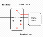
if you were to replace the feed into and out of the the DC 2Dc charger with plugs ( one male and one female) then when you need to bypass the unit and connect directly you could pull the plugs that are attached to the charger and replace them with one 'bypass' assembly of a male and female plug wired to connect the two batteries together.
Something like this...... E32570-1008 | Anderson Power Products Female 2 Way Battery Connector, 320A, 600 V | RS
 

Poey50

Well-known member
Joined
26 Apr 2016
Messages
2,318
Location
Chichester
Visit site
Why would you want to do an emergency parallel? In my system I have an lithium bank on the house circuit, an AGM battery on the separate engine start circuit. In my case the start battery is maintained by battery to battery charger from the lithium (but it could be the other way round). The third emergency switch is used to allow the lithium to start the engine or for the engine battery to run emergency loads. While it is possible to combine, that would be the only setting I wouldn't use and I can't see any situation in which I would need to.
 
Last edited:

VicS

Well-known member
Joined
13 Jul 2002
Messages
48,523
Visit site
Hi. I want to replace the VSR that came with the boat with a DC2DC charger to keep the 2 batteries (starter + domestic) separated and to apply an AGM-specific charging profile when the alternator is running.

Does anybody have any solutions for this? Ideally this could be done through a single switch,

Any advice or suggestions would be much appreciated! Many thanks.
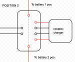
Would something like this do? Assuming you can find a suitable ON-OFF-ON switch to use as the emergency crossover switch

1676931241267.png
 

PaulRainbow

Well-known member
Joined
16 May 2016
Messages
17,056
Location
Suffolk
Visit site
Hi. I want to replace the VSR that came with the boat with a DC2DC charger to keep the 2 batteries (starter + domestic) separated and to apply an AGM-specific charging profile when the alternator is running.

Why ? Lots of boats out there with alternators charging AGM batteries.
 

William_H

Well-known member
Joined
28 Jul 2003
Messages
13,988
Location
West Australia
Visit site
I can't imagine why the negatives of the B2B need to be disconnected when paralleling batteries. You might just confirm this with maker. In which case A double pole double throw switch moving input from B2B to the jump line and a similar change over from output of B2B to that same jump line should isolate B2B and get engine start.
Or you could wire the DPDT switch to disconnect engine battery and move that connection top the house battery. Need to use the remaining switch side to disconnect supply to B2B. This has the advantage of completely disconnecting engine battery if it has a cell failure but could be a bit of concern if you tried to then revert to engine battery with engine running. ol'will
 

tymonk

Member
Joined
3 Sep 2022
Messages
54
Visit site
Thanks all for the advice. The logic is that the alternator is relatively small, so any extra charge from the algorithm would be welcome. Additionally, the boat rarely has access to shore power and I have been advised that AGM batteries should be charged according to the correct profile at least a few times a year for them to last. For the rest, there is a dual battery MPPT and the VSR effectively shorts the positives if both battery isolators are on. Therefore a DCDC seemed like a sensible solution.

I'll go back to the manufacturer to seek some further clarification, as they had previously advised that all leads, both positive and negative would need to be disconnected, even if the DCDC is off.
 

cpedw

Well-known member
Joined
1 Jun 2001
Messages
1,282
Location
Oban
Visit site
If you still need what you originally asked for, then this should do the trick with one 4 pole changeover switch. Make sure it's rated for the current! Though a simpler alternative as described above might be preferable.
switch.jpg
 

VicS

Well-known member
Joined
13 Jul 2002
Messages
48,523
Visit site
I'll go back to the manufacturer to seek some further clarification, as they had previously advised that all leads, both positive and negative would need to be disconnected, even if the DCDC is off.
Who is the manufacturer?
What sort of current rating are you looking at?
Are you looking unnecessarily at a fully isolated DC2DC charger?
Have you considered any other makes?
Would a Sterling Alternator to Battery charger do what you want without any complex switching?
 

PaulRainbow

Well-known member
Joined
16 May 2016
Messages
17,056
Location
Suffolk
Visit site
It's worth remembering that the OP wants to fit this so he can have the ability to parallel the batteries or start the engine in case of a flat/dead engine battery. So, any switch will need to be rated for the starter motor current draw. A DC changeover switch of suitable current rating will not come cheap.

A bigger alternator or an external regulator might be a better approach.
 

William_H

Well-known member
Joined
28 Jul 2003
Messages
13,988
Location
West Australia
Visit site
Op advises the alternator is relatively small. This means that the max current it can supply before it can not maintain it's regulated voltage falls off. fitment of a B2B charger will draw even more current from alternator. than at present with VSR (due to conversion losses and increase in charge voltage produced).
An amp meter in alternator charge circuit would show you just where you are on the current load of the alternator in actual practice. If indeed you are approaching the max rated current of the alternator for long periods then perhaps a larger capacity alternator is indicated. NB advertised rating of alternators is usually optimistic.
Now I know ery little about AGM batteries but I doubt that charging with a perfect charge regime will improve the life significantly to justify cost of B2B. ol'will
 

VicS

Well-known member
Joined
13 Jul 2002
Messages
48,523
Visit site
It's worth remembering that the OP wants to fit this so he can have the ability to parallel the batteries or start the engine in case of a flat/dead engine battery. So, any switch will need to be rated for the starter motor current draw. A DC changeover switch of suitable current rating will not come cheap.

I am thinking along the lines of a Blue Sea m series 3 way battery selector switch ( 1-OFF-2, but no "BOTH" position)
 

PaulRainbow

Well-known member
Joined
16 May 2016
Messages
17,056
Location
Suffolk
Visit site
I am thinking along the lines of a Blue Sea m series 3 way battery selector switch ( 1-OFF-2, but no "BOTH" position)

That's what i thought of when i saw your diagram in post #5

If it wasn't for the need to disconnect both positives and both negatives, that should work.

That said, trying to find a solution to using the B2B is a distraction, IMO. I cannot see what real benefit a B2B will be for what the OP describes in post #1. It's not going to get any more charge from the alternator and the charge settings for AGM and SLA are very similar, the best he can do is increase the charging voltage by about 0.2v (depending on the alternator.

A decent, modern alternator is going to charge at around 14.4 volts, good for AGM. Fitting a larger output alternator would possibly charge the batteries faster. But for that to be true, the existing alternator would need to be very puny, a single AGM battery isn't going to accept a massive current. If the alternator is an old style one, with low charging voltages, then it would definitely be better to change to a more modern one, or an external regulator.
 

tymonk

Member
Joined
3 Sep 2022
Messages
54
Visit site
Thanks for all the advice. I appreciate everyone trying to think along. Maybe I should have added a bit more background to explain why I thought a B2B was a good solution:

I have a dual battery MPPT (charges 1 battery up to 70% and then both equally) and the VSR shorts the positives of the MPPT when it switches on, and if both of the isolators are both off (i.e. the batteries are connected; with battery isolators I never know if on means whether the batteries are isolated or not.) So this only a problem when the engine is running and both batteries are connected, and not when the boat is sat still on its swinging mooring (where it spends most of its time). Where I bought the batteries advises charging it to the correct voltage (higher than standard lead acid) at least once a month, to prevent a memory effect and shortening its life. As it's on a swinging mooring there is no regular access to the mains.

So to me a B2B charger seemed to be a fairly easy/cheap solution for some potential charging gains from the small-ish alternator, dealing with the MPPT shorting issue and ensure that there is as much charging according to the right regime as possible. I found decently reviewed B2Bs for around £100 (e.g. Renogy), which is quite a bit cheaper than a Starling alternator-battery charger or replacing the alternator. It would be easy to fit if something like the suggestion from @VicS would work (would confirm again with manufacturer). From background reading I had also understood that VSRs were a little outdated and it was always preferable to keep the batteries as split as possible. For example, if the domestic battery has an issue (and I fail to notice), the VSR would parallel the batteries and possibly knacker the engine battery?

But if those more knowledgeable are not convinced the potential gains of the added charging regime for battery life, maybe I should stick to the VSR? (If it ain't broke, don't fix it... There is plenty of other stuff on the boat that is actually broke!) So an alternative is just to disconnect the MPPT when the engine is running or adding an NC relay to the ignition for the MPPT.

Anyway I would appreciate any views in light of added context above.
 

PaulRainbow

Well-known member
Joined
16 May 2016
Messages
17,056
Location
Suffolk
Visit site
You have created an anomaly by having a VSR and a dual MPPT controller and adding a B2B makes matters worse.

Alpha batteries claim that AGM batteries must be charged at 14.6v-14.8v is nonsense. Different manufacturers will quote different figures, but 14.4v is generally considered acceptable. Alphas claim that charging at 14.4v will cause a "memory effect" is complete and utter nonsense.

When your isolators are off they should isolate the batteries from the loads, but charging should still work. The VSR should be connected to the batteries, not after the isolators.

1) If your MPPT controller allows just one battery to be connected you could connect to the AGM battery and leave the VSR in place. If it doesn't allow only one battery to be connected you could swap for one that does. If you wanted to charge the AGM at a slightly higher voltage you could set the MPPT to do so. Again, if the controller doesn't allow you to do so, change it for one that does.

2) You could fit a changeover relay to the ign circuit, NC connected to the battery negative terminal of the MPPT controller and the NO terminal connected to the VSR negative. BUT ONLY if the MPPT controller allows disconnecting the battery, not all do. Plus, the relay needs to be rated for at least the max solar charge current.

3) You could swap the VSR for something like a Victron Argoget

I'd favour option 1.
 

tymonk

Member
Joined
3 Sep 2022
Messages
54
Visit site
Thanks @PaulRainbow. Have added a diagram in case this clarifies things further. The VSR is between the isolators and the loads. Most of this was inherited and it was a probate sale so it has taken a while to figure out how things are wired and why they are wired in that way (the former owner was an electrical engineer I am told and did the wiring of most boats in the yard).

So charging (via the panels) does happen if the batteries are isolated. The MPPT can have 1 battery connected, but seeing how the VSR is connected I could leave both batteries connected if the aim is to leave the VSR in place. There is nothing specific about disconnecting batteries in the manual, but the set up instructions require the connection of the panels before the batteries, so I would assume so?
 

Attachments

  • Screenshot 2023-02-23 at 16.21.21.png
    Screenshot 2023-02-23 at 16.21.21.png
    388.3 KB · Views: 20

PaulRainbow

Well-known member
Joined
16 May 2016
Messages
17,056
Location
Suffolk
Visit site
Thanks @PaulRainbow. Have added a diagram in case this clarifies things further. The VSR is between the isolators and the loads. Most of this was inherited and it was a probate sale so it has taken a while to figure out how things are wired and why they are wired in that way (the former owner was an electrical engineer I am told and did the wiring of most boats in the yard).

So charging (via the panels) does happen if the batteries are isolated. The MPPT can have 1 battery connected, but seeing how the VSR is connected I could leave both batteries connected if the aim is to leave the VSR in place. There is nothing specific about disconnecting batteries in the manual, but the set up instructions require the connection of the panels before the batteries, so I would assume so?

That's helpful. It seems both batteries are AGM ? From post #1 i had assumed the engine battery was SLA.

Really easy to resolve your issues/concerns:

1) Connect the MPPT controller to the domestic battery.
2) Move the VSR connections to the battery terminals of the isolator switches.

The VSR then makes sure the batteries get charged by solar or the engine, there is no "clash" between the VSR and the MPPT.

You can then, if the MPPT allows, increase the charging voltage a little. If it does not allow, you have the choice to settle for 14.4v (assuming that's what the controller puts out) or to change the controller for one that is more configurable.
 

tymonk

Member
Joined
3 Sep 2022
Messages
54
Visit site
Thank you. Yes, sorry: They are both AGM. I have not opened up the VSR yet but as in the diagram the main wire to the domestic load comes out of it. So I suppose that would need to be moved to the non-battery side of the isolator and then I should be good to go.
 
Top